- 您現(xiàn)在的位置:買賣IC網(wǎng) > PDF目錄68011 > MD82C54-10/B (INTERSIL CORP) 3 TIMER(S), PROGRAMMABLE TIMER, CDIP24 PDF資料下載
參數(shù)資料
| 型號: | MD82C54-10/B |
| 廠商: | INTERSIL CORP |
| 元件分類: | 時(shí)鐘/數(shù)據(jù)恢復(fù)及定時(shí)提取 |
| 英文描述: | 3 TIMER(S), PROGRAMMABLE TIMER, CDIP24 |
| 封裝: | CERDIP-24 |
| 文件頁數(shù): | 17/19頁 |
| 文件大小: | 380K |
| 代理商: | MD82C54-10/B |
7
read or write or programming operations of other Counters
may be inserted between them.
Another feature of the 82C54 is that reads and writes of the
same Counter may be interleaved; for example, if the
Counter is programmed for two byte counts, the following
sequence is valid.
1. Read least significant byte.
2. Write new least significant byte.
3. Read most significant byte.
4. Write new most significant byte.
If a counter is programmed to read or write two-byte counts,
the following precaution applies: A program MUST NOT
transfer control between reading the first and second byte to
another routine which also reads from that same Counter.
Otherwise, an incorrect count will be read.
Read-Back Command
The read-back command allows the user to check the count
value, programmed Mode, and current state of the OUT pin
and Null Count flag of the selected counter(s).
The command is written into the Control Word Register and
has the format shown in Figure 5. The command applies to
the counters selected by setting their corresponding bits D3,
D2, D1 = 1.
The read-back command may be used to latch multiple
counter output latches (OL) by setting the COUNT bit D5 = 0
and selecting the desired counter(s). This signal command is
functionally equivalent to several counter latch commands,
one for each counter latched. Each counter’s latched count
is held until it is read (or the counter is reprogrammed). That
counter is automatically unlatched when read, but other
counters remain latched until they are read. If multiple count
read-back commands are issued to the same counter with-
out reading the count, all but the first are ignored; i.e., the
count which will be read is the count at the time the first
read-back command was issued.
The read-back command may also be used to latch status
information of selected counter(s) by setting STATUS bit D4
= 0. Status must be latched to be read; status of a counter is
accessed by a read from that counter.
The counter status format is shown in Figure 6. Bits D5
through D0 contain the counter’s programmed Mode exactly
as written in the last Mode Control Word. OUTPUT bit D7
contains the current state of the OUT pin. This allows the
user to monitor the counter’s output via software, possibly
eliminating some hardware from a system.
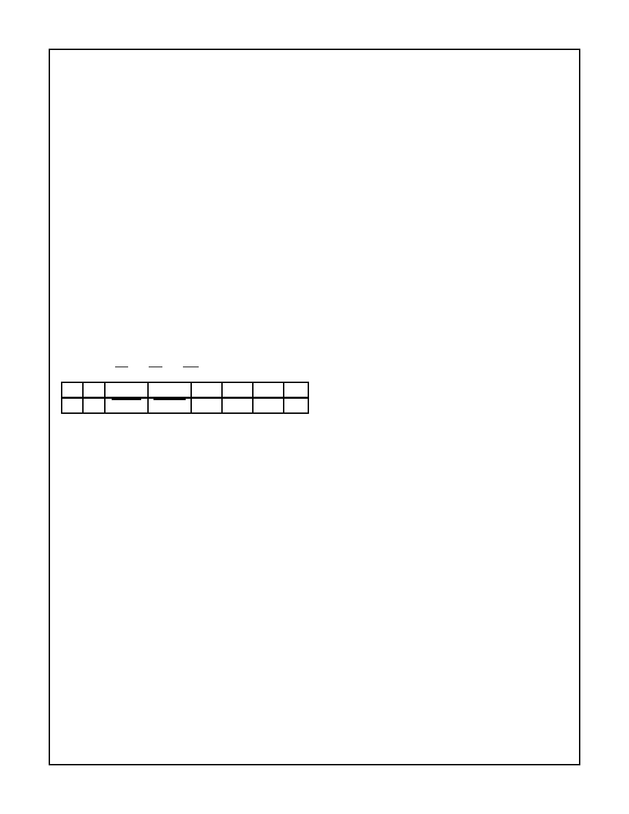
A0, A1 = 11; CS = 0; RD = 1; WR = 0
D7
D6
D5
D4
D3
D2
D1
D0
1
COUNT
STATUS
CNT 2 CNT 1 CNT 0
0
D5: 0 = Latch count of selected Counter (s)
D4: 0 = Latch status of selected Counter(s)
D3: 1 = Select Counter 2
D2: 1 = Select Counter 1
D1: 1 = Select Counter 0
D0: Reserved for future expansion; Must be 0
FIGURE 5. READ-BACK COMMAND FORMAT
82C54
相關(guān)PDF資料 |
PDF描述 |
|---|---|
| MD82C54-12/B | 3 TIMER(S), PROGRAMMABLE TIMER, CDIP24 |
| MR82C54/883 | 3 TIMER(S), PROGRAMMABLE TIMER, CQCC28 |
| MD82C54/883 | 3 TIMER(S), PROGRAMMABLE TIMER, CDIP24 |
| MR82C84A/883 | 25 MHz, PROC SPECIFIC CLOCK GENERATOR, CQCC20 |
| MR83C154DCXXX-12/883D | 8-BIT, MROM, 12 MHz, MICROCONTROLLER, CQCC44 |
相關(guān)代理商/技術(shù)參數(shù) |
參數(shù)描述 |
|---|---|
| MD82C54-12 | 制造商:INTERSIL 制造商全稱:Intersil Corporation 功能描述:CMOS Programmable Interval Timer |
| MD82C54-12B | 制造商:INTERSIL 制造商全稱:Intersil Corporation 功能描述:CMOS Programmable Interval Timer |
| MD82C54B | 制造商: 功能描述: 制造商:undefined 功能描述: |
| MD82C54Q | 制造商: 功能描述: 制造商:undefined 功能描述: |
| MD82C55/R | 制造商:Rochester Electronics LLC 功能描述:- Bulk |
發(fā)布緊急采購,3分鐘左右您將得到回復(fù)。