- 您現(xiàn)在的位置:買賣IC網(wǎng) > PDF目錄383596 > MD900 (PerkinElmer Inc.) Ultra High Sensitivity Gateable Channel Photomultiplier DC-Modules PDF資料下載
參數(shù)資料
| 型號: | MD900 |
| 廠商: | PerkinElmer Inc. |
| 英文描述: | Ultra High Sensitivity Gateable Channel Photomultiplier DC-Modules |
| 中文描述: | 超高靈敏度Gateable通道光電倍增管直流模塊 |
| 文件頁數(shù): | 2/9頁 |
| 文件大小: | 138K |
| 代理商: | MD900 |
SN54ALS109A, SN54AS109A, SN74ALS109A, SN74AS109A
DUAL J-K POSITIVE-EDGE-TRIGGERED FLIP-FLOPS
WITH CLEAR AND PRESET
SDAS198B – APRIL 1982 – REVISED AUGUST 1995
2
POST OFFICE BOX 655303
DALLAS, TEXAS 75265
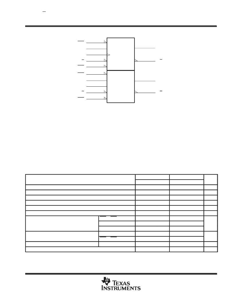
logic symbol
S
5
1J
2
1J
4
1CLK
1K
3
1Q
6
7
C1
11
14
2J
12
2CLK
13
2Q
10
9
1PRE
2PRE
1CLR
2K
1Q
2Q
R
1
1K
15
2CLR
This symbol is in accordance with ANSI/IEEE Std 91-1984 and IEC Publication 617-12.
Pin numbers shown are for the D, J, and N packages.
absolute maximum ratings over operating free-air temperature range (unless otherwise noted)
Supply voltage, V
CC
Input voltage, V
I
Operating free-air temperature range, T
A
: SN54ALS109A
7 V
7 V
. . . . . . . . . . . . . . . . . . . . . . . . . . . . . . . . . . . . . . . . . . . . . . . . . . . . . . . . . . . . . . . . . . . . . . . .
. . . . . . . . . . . . . . . . . . . . . . . . . . . . . . . . . . . . . . . . . . . . . . . . . . . . . . . . . . . . . . . . . . . . . . . . . . . .
. . . . . . . . . . . . . . . . . . . . . . . . . . .
SN74ALS109A
. . . . . . . . . . . . . . . . . . . . . . . . . . . . . . .
Storage temperature range
. . . . . . . . . . . . . . . . . . . . . . . . . . . . . . . . . . . . . . . . . . . . . . . . . . . . . . .
–55
°
C to 125
°
C
0
°
C to 70
°
C
–65
°
C to 150
°
C
Stresses beyond those listed under “absolute maximum ratings” may cause permanent damage to the device. These are stress ratings only, and
functional operation of the device at these or any other conditions beyond those indicated under “recommended operating conditions” is not
implied. Exposure to absolute-maximum-rated conditions for extended periods may affect device reliability.
recommended operating conditions
SN54ALS109A
SN74ALS109A
UNIT
MIN
NOM
MAX
MIN
NOM
MAX
VCC
VIH
VIL
IOH
IOL
fclock
Supply voltage
4.5
5
5.5
4.5
5
5.5
V
High-level input voltage
2
2
V
Low-level input voltage
0.7
0.8
V
High-level output current
–0.4
–0.4
mA
Low-level output current
4
8
mA
Clock frequency
0
30
0
34
MHz
PRE or CLR low
15
15
tw
Pulse duration
CLK high
16.5
14.5
ns
CLK low
16.5
14.5
tsu
Set p time before CLK
Setup time before CLK
↑
Data
15
15
ns
PRE or CLR inactive
10
10
th
TA
Hold time after CLK
↑
Operating free-air temperature
Data
0
0
ns
°
C
–55
125
0
70
相關(guān)PDF資料 |
PDF描述 |
|---|---|
| MDFB51 | Fast Recovery Diode |
| MDFB5120 | Fast Recovery Diode |
| MDFB5122 | Fast Recovery Diode |
| MDFB5124 | Fast Recovery Diode |
| MDFB5125 | Fast Recovery Diode |
相關(guān)代理商/技術(shù)參數(shù) |
參數(shù)描述 |
|---|---|
| MD90A | 制造商:未知廠家 制造商全稱:未知廠家 功能描述:電焊機專用整流模塊MD90A1600V |
| MD90A1600V | 制造商:未知廠家 制造商全稱:未知廠家 功能描述:光伏防反二極管模塊MD90A1600V |
| MD90FF18 | 制造商:VMI 制造商全稱:VMI 功能描述:DO-215 Style Rectifiers - 1,800V |
| MD90FF18J | 制造商:VMI 制造商全稱:VMI 功能描述:DO-214 Style Rectifiers - 1,800V |
| MD90FF25 | 制造商:VMI 制造商全稱:VMI 功能描述:Spice Model |
發(fā)布緊急采購,3分鐘左右您將得到回復(fù)。