- 您現(xiàn)在的位置:買賣IC網(wǎng) > PDF目錄379319 > MHPM6B15E60D3 (MOTOROLA INC) Hybrid Power Module PDF資料下載
參數(shù)資料
| 型號(hào): | MHPM6B15E60D3 |
| 廠商: | MOTOROLA INC |
| 元件分類: | IGBT 晶體管 |
| 英文描述: | Hybrid Power Module |
| 中文描述: | 15 A, 600 V, N-CHANNEL IGBT |
| 文件頁(yè)數(shù): | 2/5頁(yè) |
| 文件大小: | 129K |
| 代理商: | MHPM6B15E60D3 |
2
Motorola IGBT Device Data
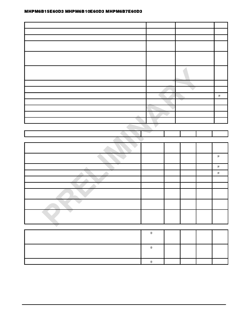
MAXIMUM DEVICE RATINGS
(TJ = 25
°
C unless otherwise noted)
Rating
Symbol
Value
Unit
Average Converter Output Current (Peak–to–Average ratio of 10, TC = 95
°
C)
Continuous Input Rectifier Current (TC = 25
°
C)
Non–Repetitive Peak Input Rectifier Forward Surge Current (2)
(TJ = 95
°
C prior to start of surge)
IOmax
IDC
IFSM
20
A
20
A
475
A
IGBT Power Dissipation per die (TC = 95
°
C)
7E60
10E60
15E60
PD
14
17
23
W
Free–Wheeling Diode Power Dissipation per die (TC = 95
°
C)
7E60
10E60
15E60
PD
7.4
9.0
13
W
Input Rectifier Power Dissipation per die (TC = 95
°
C)
Junction Temperature Range
PD
TJ
tsc
VISO
TC
Tstg
—
13
W
–40 to +150
°
C
Short Circuit Duration (VCE = 400 V, TJ = 125
°
C)
Isolation Voltage, pin to baseplate
10
s
2500
Vac
Operating Case Temperature Range
–40 to +95
°
C
Storage Temperature Range
–40 to +150
°
C
Mounting Torque — Heat Sink Mounting Holes
12
lb–in
ELECTRICAL CHARACTERISTICS
(TJ = 25
°
C unless otherwise noted)
Characteristic
Symbol
Min
Typ
Max
Unit
DC AND SMALL SIGNAL CHARACTERISTICS
Input Rectifier Forward Voltage (I = 15 A)
TJ = 125
°
C
VF
—
—
0.97
0.88
1.2
—
V
Maximum Instantaneous Reverse Current (V = 900 V)
TJ = 150
°
C
IR
—
—
50
3000
—
—
A
Gate–Emitter Leakage Current (VCE = 0 V, VGE =
±
20 V)
Collector–Emitter Leakage Current (VCE = 600 V, VGE = 0 V)
Gate–Emitter Threshold Voltage (VCE = VGE, IC = 1.0 mA)
Collector–Emitter Breakdown Voltage (IC = 10 mA, VGE = 0 V)
Collector–Emitter Saturation Voltage (IC = ICmax, VGE = 15 V)
TJ = 125
°
C
IGES
ICES
VGE(th)
V(BR)CES
VCE(SAT)
—
—
±
50
A
—
5.0
100
A
4.0
6.0
8.0
V
600
—
—
V
—
—
2.0
1.8
2.4
—
V
Free–Wheeling Diode Forward Voltage (IF = IFmax, VGE = 0 V)
TJ = 125
°
C
VF
—
—
2.0
1.8
2.3
—
V
Input Capacitance (VGE = 0 V, VCE = 10 V, f = 1.0 MHz)
7E60
10E60
15E60
Cies
—
—
—
780
1020
1605
—
—
—
pF
THERMAL CHARACTERISTICS (EACH DIE)
Thermal Resistance — IGBT
7E60
10E60
15E60
RJC
—
—
—
3.1
2.6
1.9
3.8
3.2
2.4
°
C/W
Thermal Resistance — Free–Wheeling Diode
7E60
10E60
15E60
RJC
—
—
—
6.0
4.8
3.4
7.5
6.1
4.2
°
C/W
Thermal Resistance — Input Rectifier
RJC
—
3.4
4.2
°
C/W
(2) 1.0 ms = 10% pulse width (tw 10%)
相關(guān)PDF資料 |
PDF描述 |
|---|---|
| MHPM6B2A60D | DIODE ZENER 150MW 4.7V 0603 |
| MHPM6B10A60D | M39012 MIL RF CONNECTOR |
| MHPM7A10E60DC3 | Hybrid Power Module |
| MHPM7A10S120DC3 | Hybrid Power Module |
| MHPM7A15A60A | Hybrid Power Module |
相關(guān)代理商/技術(shù)參數(shù) |
參數(shù)描述 |
|---|---|
| MHPM6B15N120SL | 制造商:MOTOROLA 制造商全稱:Motorola, Inc 功能描述:Hybrid Power Module |
| MHPM6B15N120SS | 制造商:MOTOROLA 制造商全稱:Motorola, Inc 功能描述:Hybrid Power Module |
| MHPM6B20E60D3 | 制造商:MOTOROLA 制造商全稱:Motorola, Inc 功能描述:Hybrid Power Module |
| MHPM6B25N120SL | 制造商:MOTOROLA 制造商全稱:Motorola, Inc 功能描述:Hybrid Power Module |
| MHPM6B25N120SS | 制造商:MOTOROLA 制造商全稱:Motorola, Inc 功能描述:Hybrid Power Module |
發(fā)布緊急采購(gòu),3分鐘左右您將得到回復(fù)。