- 您現(xiàn)在的位置:買賣IC網(wǎng) > PDF目錄383612 > MIC5031 (Micrel Semiconductor,Inc.) High-Speed High-Side MOSFET Driver(高速高邊MOS場效應管驅動器) PDF資料下載
參數(shù)資料
| 型號: | MIC5031 |
| 廠商: | Micrel Semiconductor,Inc. |
| 英文描述: | High-Speed High-Side MOSFET Driver(高速高邊MOS場效應管驅動器) |
| 中文描述: | 高速高邊MOSFET驅動器(高速高邊馬鞍山場效應管驅動器) |
| 文件頁數(shù): | 6/8頁 |
| 文件大小: | 88K |
| 代理商: | MIC5031 |
MIC5031
Applications Information
Power-Up Sequence
The supply voltage (V
DD
) must be applied to VDD before EN
is asserted. If EN is not required for the application, an RC
network must be used to delay the voltage rise applied to EN
with respect to VDD. See Figure 1.
Micrel
MIC5031
6
August 1999
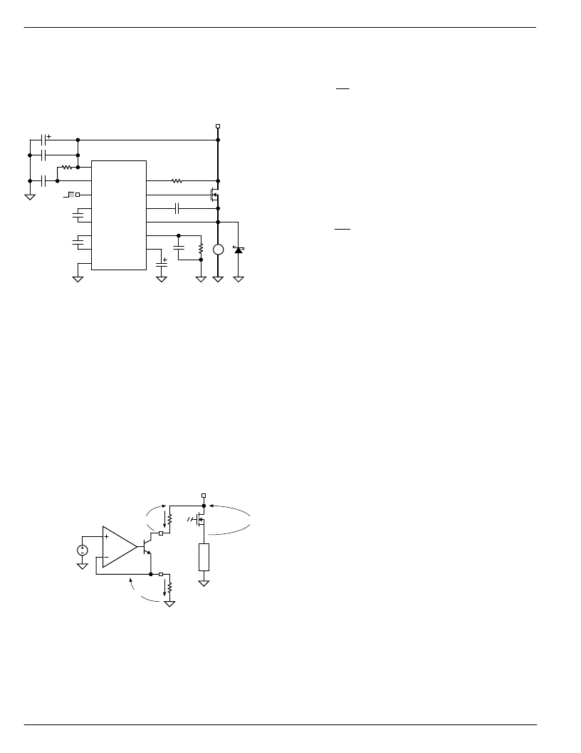
On
Off
FLG
RV
G
VDD
EN
CTL
+4.5V to +30V
MIC5031
CB
CP1+
S
CP1–
RI
CP2+
CS
CP2–
DLY
GND
15μF
12k*
0.1μF
0.01μF
0.01μF
7
4
3
10
8
11
9
5
2
6
15
13
12
16
14
1
IRF540
0.1μF
M
2N5822
100μF
100nF
0.01μF
10k
Figure 1. Enable Application
Refer to “Typical Application” for controlling EN from open-
collector or open-drain logic. The 10k resistor and 0.01
μ
F
capacitor connected to VDD, GND, and EN keep EN low
during power up before the open-collector or open-drain logic
becomes active.
The 10k resistor and 0.01
μ
F capacitor can be omitted if EN
is held low by the external logic until VDD is powered.
Overcurrent Detection
Using the MOSFET manufacturer’s data and the maximum
allowable load current, determine the maximum drain-to-
source voltage drop, V
DS
, that will occur across the external
MOSFET in normal operation. This will also be the reference
voltage and the overcurrent trip voltage, V
R1
.
V
R1
= maximum R
DS(on)
×
maximum load current
Supply
1.23V
Bandgap
Reference
RV
RI
External
N-Channel
MOSFET
L
V
DS
V
R1
I
R2
R1
R2
1.23V
I
R2
Figure 2. Resistor Calculations
Reference Current Resistor
Resistor R2 sets the reference current. For most applica-
tions, a reference current of 100
μ
A is suggested.
R2
R1
I
R2
=
where:
R2 = reference current resistor (
)
I
R2
= reference current (A) [R2 = 12k
for
approximately 100
μ
A]
Reference Voltage Resistor
The reference voltage resistor value is calculated from the
reference current and the reference voltage (overcurrent
drop voltage).
R1
V
I
R2
R1
=
where:
R1 = reference voltage resistor (
)
V
R1
= reference voltage (V) [see above]
I
R2
= reference current (A) [see above]
Overcurrent Delay Capacitor
For lamp switching applications, the delay capacitor (C
DLY
)
may be as high as several microfarads. Lamps often have an
inrush current of 10
×
their steady-state operating current. In
PWM applications, pay attention to the input frequency vs.
the overcurrent delay. They can conflict with each other if not
properly planned.
相關PDF資料 |
PDF描述 |
|---|---|
| MIC5031BM | High-Speed High-Side MOSFET Driver |
| MIC50398 | Replaced by PTN78060W,PTN78060H : |
| MIC50398CN | Replaced by PTN78060W,PTN78060H : |
| MIC50399CN | Replaced by PTN78060W,PTN78060H : |
| MIC5158 | Super LDO Regulator Controller(超低壓差穩(wěn)壓器控制器) |
相關代理商/技術參數(shù) |
參數(shù)描述 |
|---|---|
| MIC5031BM | 制造商:MICREL 制造商全稱:Micrel Semiconductor 功能描述:High-Speed High-Side MOSFET Driver |
| MIC50395 | 制造商:MICREL 制造商全稱:Micrel Semiconductor 功能描述:Six Decade Counter / Display Decoder Not Recommended for New Designs |
| MIC50395CN | 制造商:MICREL 制造商全稱:Micrel Semiconductor 功能描述:Six Decade Counter / Display Decoder Not Recommended for New Designs |
| MIC50396 | 制造商:MICREL 制造商全稱:Micrel Semiconductor 功能描述:Six Decade Counter / Display Decoder Not Recommended for New Designs |
| MIC50396CN | 制造商:MICREL 制造商全稱:Micrel Semiconductor 功能描述:Six Decade Counter / Display Decoder Not Recommended for New Designs |
發(fā)布緊急采購,3分鐘左右您將得到回復。