- 您現(xiàn)在的位置:買賣IC網(wǎng) > PDF目錄377970 > ML4804IP (FAIRCHILD SEMICONDUCTOR CORP) Power Factor Correction and PWM Controller Combo PDF資料下載
參數(shù)資料
| 型號: | ML4804IP |
| 廠商: | FAIRCHILD SEMICONDUCTOR CORP |
| 元件分類: | 穩(wěn)壓器 |
| 英文描述: | Power Factor Correction and PWM Controller Combo |
| 中文描述: | 1 A POWER FACTOR CONTROLLER WITH POST REGULATOR, 250 kHz SWITCHING FREQ-MAX, PDIP16 |
| 封裝: | PLASTIC, DIP-16 |
| 文件頁數(shù): | 11/14頁 |
| 文件大?。?/td> | 145K |
| 代理商: | ML4804IP |
ML4804
REV. 1.0.2 3/9/2001
11
No voltage error amplifier is included in the PWM stage of
the ML4804, as this function is generally performed on the
output side of the PWM
’
s isolation boundary. To facilitate
the design of optocoupler feedback circuitry, an offset has
been built into the PWM
’
s RAMP 2 input which allows
V
DC
to command a zero percent duty cycle for input
voltages below 1.25V.
PWM Current Limit
The DC I
LIMIT
pin is a direct input to the cycle-by-cycle
current limiter for the PWM section. Should the input
voltage at this pin ever exceed 1V, the output of the PWM
will be disabled until the output flip-flop is reset by the
clock pulse at the start of the next PWM power cycle.
V
IN
OK Comparator
The V
IN
OK comparator monitors the DC output of the
PFC and inhibits the PWM if this voltage on V
FB
is less
than its nominal 2.45V. Once this voltage reaches 2.45V,
which corresponds to the PFC output capacitor being
charged to its rated boost voltage, the soft-start begins.
PWM Control (RAMP 2)
When the PWM section is used in current mode, RAMP 2
is generally used as the sampling point for a voltage
representing the current in the primary of the PWM
’
s
output transformer, derived either by a current sensing
resistor or a current transformer. In voltage mode, it is the
input for a ramp voltage generated by a second set of
timing components (R
RAMP2
, C
RAMP2
), that will have a
minimum value of zero volts and should have a peak
value of approximately 5V. In voltage mode operation,
feedforward from the PFC output buss is an excellent way
to derive the timing ramp for the PWM stage.
Soft Start
Start-up of the PWM is controlled by the selection of the
external capacitor at SS. A current source of 25
μ
A
supplies the charging current for the capacitor, and start-
up of the PWM begins at 1.25V. Start-up delay can be
programmed by the following equation:
(6)
where C
SS
is the required soft start capacitance, and
t
DELAY
is the desired start-up delay.
It is important that the time constant of the PWM soft-start
allow the PFC time to generate sufficient output power for
the PWM section. The PWM start-up delay should be at
least 5ms.
Solving for the minimum value of C
SS
:
(6a)
Caution should be exercised when using this minimum
soft start capacitance value because premature charging of
the SS capacitor and activation of the PWM section can
result if V
FB
is in the hysteresis band of the V
IN
OK
comparator at start-up. The magnitude of V
FB
at start-up is
related both to line voltage and nominal PFC output
voltage. Typically, a 1.0
μ
F soft start capacitor will allow
time for V
FB
and PFC out to reach their nominal values
prior to activation of the PWM section at line voltages
between 90Vrms and 265Vrms.
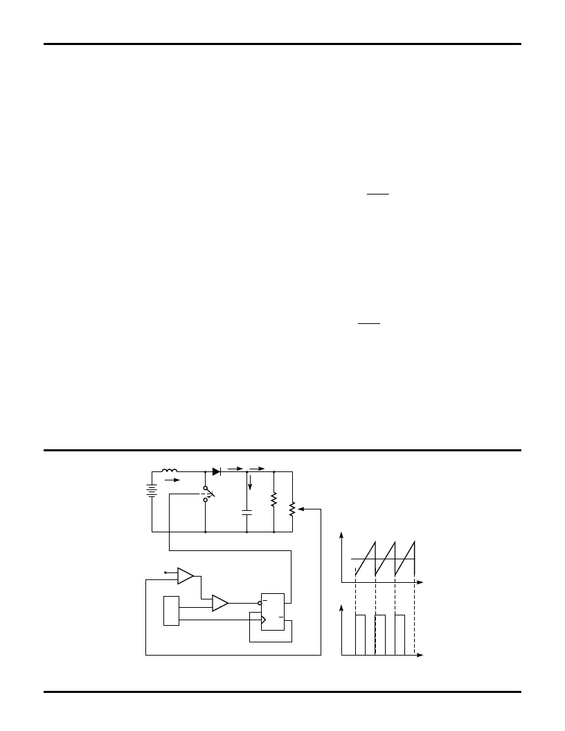
Figure 4. Typical Trailing Edge Control Scheme
FUNCTIONAL DESCRIPTION
(Continued)
RAMP
VEAO
TIME
VSW1
TIME
REF
EA
–
+
–
+
OSC
DFF
R
D
Q
Q
CLK
U1
RAMP
CLK
U4
U3
C1
RL
I4
SW2
SW1
+
DC
I1
I2
I3
VIN
L1
U2
%&
=
×
μ
!'
=
×
=
μ
相關(guān)PDF資料 |
PDF描述 |
|---|---|
| ML4804IS | Power Factor Correction and PWM Controller Combo |
| ML4804 | Power Factor Correction and PWM Controller Combo(功率因數(shù)校正器和PWM控制器組合芯片) |
| ML4805 | Variable Feedforward PFC/PWM Controller Combo |
| ML4805CP | Variable Feedforward PFC/PWM Controller Combo |
| ML4805CS | Variable Feedforward PFC/PWM Controller Combo |
相關(guān)代理商/技術(shù)參數(shù) |
參數(shù)描述 |
|---|---|
| ML4804IS | 制造商:MICRO-LINEAR 制造商全稱:MICRO-LINEAR 功能描述:Power Factor Correction and PWM Controller Combo |
| ML4805 | 制造商:MICRO-LINEAR 制造商全稱:MICRO-LINEAR 功能描述:Variable Feedforward PFC/PWM Controller Combo |
| ML4805CP | 功能描述:功率因數(shù)校正 IC DIP-18 RoHS:否 制造商:Fairchild Semiconductor 開關(guān)頻率:300 KHz 最大功率耗散: 最大工作溫度:+ 125 C 安裝風(fēng)格:SMD/SMT 封裝 / 箱體:SOIC-8 封裝:Reel |
| ML4805CS | 功能描述:功率因數(shù)校正 IC SOIC-WIDE-18 RoHS:否 制造商:Fairchild Semiconductor 開關(guān)頻率:300 KHz 最大功率耗散: 最大工作溫度:+ 125 C 安裝風(fēng)格:SMD/SMT 封裝 / 箱體:SOIC-8 封裝:Reel |
| ML4805CSX | 功能描述:功率因數(shù)校正 IC SOIC-WIDE-18 RoHS:否 制造商:Fairchild Semiconductor 開關(guān)頻率:300 KHz 最大功率耗散: 最大工作溫度:+ 125 C 安裝風(fēng)格:SMD/SMT 封裝 / 箱體:SOIC-8 封裝:Reel |
發(fā)布緊急采購,3分鐘左右您將得到回復(fù)。