- 您現(xiàn)在的位置:買賣IC網(wǎng) > PDF目錄25641 > MR80C32-12P883D (TEMIC SEMICONDUCTORS) 8-BIT, 12 MHz, MICROCONTROLLER, CQCC44 PDF資料下載
參數(shù)資料
| 型號: | MR80C32-12P883D |
| 廠商: | TEMIC SEMICONDUCTORS |
| 元件分類: | 微控制器/微處理器 |
| 英文描述: | 8-BIT, 12 MHz, MICROCONTROLLER, CQCC44 |
| 文件頁數(shù): | 85/91頁 |
| 文件大小: | 19688K |
| 代理商: | MR80C32-12P883D |
第1頁第2頁第3頁第4頁第5頁第6頁第7頁第8頁第9頁第10頁第11頁第12頁第13頁第14頁第15頁第16頁第17頁第18頁第19頁第20頁第21頁第22頁第23頁第24頁第25頁第26頁第27頁第28頁第29頁第30頁第31頁第32頁第33頁第34頁第35頁第36頁第37頁第38頁第39頁第40頁第41頁第42頁第43頁第44頁第45頁第46頁第47頁第48頁第49頁第50頁第51頁第52頁第53頁第54頁第55頁第56頁第57頁第58頁第59頁第60頁第61頁第62頁第63頁第64頁第65頁第66頁第67頁第68頁第69頁第70頁第71頁第72頁第73頁第74頁第75頁第76頁第77頁第78頁第79頁第80頁第81頁第82頁第83頁第84頁當(dāng)前第85頁第86頁第87頁第88頁第89頁第90頁第91頁

43
7707F–AVR–11/10
AT90USB82/162
Mode is equivalent to Standy Mode, but is also conserved for compatibility purpose. From
Extended Standby mode, the device wakes up in six clock cycle.
Notes:
1. Only recommended with external crystal or resonator selected as clock source.
Notes:
1. For INT7:4, only level interrupt.
Notes:
1. Asynchronous USB interrupt is WAKEUPI only.
8.6
Power Reduction Register
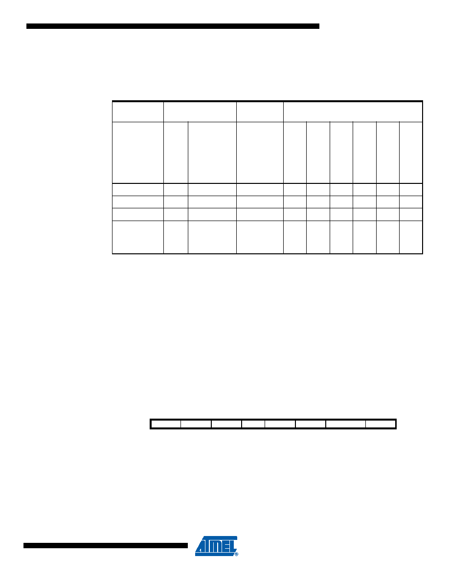
The Power Reduction Register, PRR, provides a method to stop the clock to individual peripher-
als to reduce power consumption. The current state of the peripheral is frozen and the I/O
registers can not be read or written. Resources used by the peripheral when stopping the clock
will remain occupied, hence the peripheral should in most cases be disabled before stopping the
clock. Waking up a module, which is done by clearing the bit in PRR, puts the module in the
same state as before shutdown.
Module shutdown can be used in Idle mode and Active mode to significantly reduce the overall
power consumption.
8.6.1
Power Reduction Register 0 - PRR0
Bit 7-6 - Reserved bits
These bits are reserved and will always read as zero.
Bit 5 - PRTIM0: Power Reduction Timer/Counter0
Writing a logic one to this bit shuts down the Timer/Counter0 module. When the Timer/Counter0
is enabled, operation will continue like before the shutdown.
Table 8-2.
Active Clock Domains and Wake-up Sources in the Different Sleep Modes.
Active Clock
Domains
Oscillators
Wake-up Sources
Sleep Mode
cl
k
CPU
cl
k
FLASH
cl
k
IO
Ma
in
Clo
c
k
Sour
ce
Enab
led
IN
T7:
0
and
PC
INT12-0
SPM/
EEPR
O
M
R
ead
y
W
D
T
Int
e
rrupt
Oth
e
rI/O
U
S
B
Sync
hr
ono
us
Interrupts
U
S
B
Asyn
c
h
on
ou
s
Interrupts
Idle
X
XX
XXXX
Power-down
XX
Power-save
XX
Standby(1)
XX
Extended
Standby
XX
Bit
7654
3
2
1
0
-
PRTIM0
–
PRTIM1
PRSPI
-
PRR0
Read/Write
R/W
R
R/W
R
R/W
Initial Value
0000
0
相關(guān)PDF資料 |
PDF描述 |
|---|---|
| MQ80C32-16SHXXX:RD | 8-BIT, 16 MHz, MICROCONTROLLER, CQFP44 |
| MF180C31-16R | 8-BIT, 16 MHz, MICROCONTROLLER, PQFP44 |
| MD80C52TXXX-36P883D | 8-BIT, MROM, 36 MHz, MICROCONTROLLER, CDIP40 |
| MD80C32-30/883:D | 8-BIT, 30 MHz, MICROCONTROLLER, CDIP40 |
| MQ80C52EXXX-20P883R | 8-BIT, MROM, 20 MHz, MICROCONTROLLER, CQFP44 |
相關(guān)代理商/技術(shù)參數(shù) |
參數(shù)描述 |
|---|---|
| MR80C32-16 | 制造商:未知廠家 制造商全稱:未知廠家 功能描述:8-Bit Microcontroller |
| MR80C32-20 | 制造商:未知廠家 制造商全稱:未知廠家 功能描述:8-Bit Microcontroller |
| MR80C32-25 | 制造商:未知廠家 制造商全稱:未知廠家 功能描述:8-Bit Microcontroller |
| MR80C32-30 | 制造商:未知廠家 制造商全稱:未知廠家 功能描述:8-Bit Microcontroller |
| MR80C32-36 | 制造商:未知廠家 制造商全稱:未知廠家 功能描述:8-Bit Microcontroller |
發(fā)布緊急采購,3分鐘左右您將得到回復(fù)。