- 您現(xiàn)在的位置:買賣IC網(wǎng) > PDF目錄45402 > MSP430CG4616IZQW (TEXAS INSTRUMENTS INC) 16-BIT, FLASH, 8 MHz, RISC MICROCONTROLLER, PBGA113 PDF資料下載
參數(shù)資料
| 型號: | MSP430CG4616IZQW |
| 廠商: | TEXAS INSTRUMENTS INC |
| 元件分類: | 微控制器/微處理器 |
| 英文描述: | 16-BIT, FLASH, 8 MHz, RISC MICROCONTROLLER, PBGA113 |
| 封裝: | PLASTIC, BGA-113 |
| 文件頁數(shù): | 71/110頁 |
| 文件大?。?/td> | 1605K |
| 代理商: | MSP430CG4616IZQW |
第1頁第2頁第3頁第4頁第5頁第6頁第7頁第8頁第9頁第10頁第11頁第12頁第13頁第14頁第15頁第16頁第17頁第18頁第19頁第20頁第21頁第22頁第23頁第24頁第25頁第26頁第27頁第28頁第29頁第30頁第31頁第32頁第33頁第34頁第35頁第36頁第37頁第38頁第39頁第40頁第41頁第42頁第43頁第44頁第45頁第46頁第47頁第48頁第49頁第50頁第51頁第52頁第53頁第54頁第55頁第56頁第57頁第58頁第59頁第60頁第61頁第62頁第63頁第64頁第65頁第66頁第67頁第68頁第69頁第70頁當前第71頁第72頁第73頁第74頁第75頁第76頁第77頁第78頁第79頁第80頁第81頁第82頁第83頁第84頁第85頁第86頁第87頁第88頁第89頁第90頁第91頁第92頁第93頁第94頁第95頁第96頁第97頁第98頁第99頁第100頁第101頁第102頁第103頁第104頁第105頁第106頁第107頁第108頁第109頁第110頁
MSP430xG461x
MIXED SIGNAL MICROCONTROLLER
SLAS508I APRIL 2006 REVISED MARCH 2011
63
POST OFFICE BOX 655303
DALLAS, TEXAS 75265
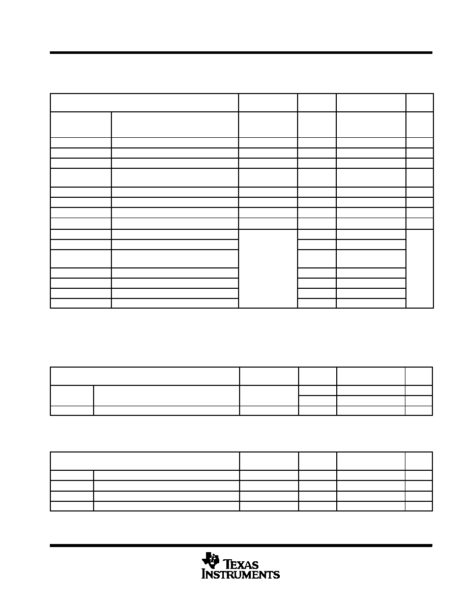
electrical characteristics over recommended operating free-air temperature (unless otherwise
noted)
flash memory (MSP430FG461x devices only)
PARAMETER
TEST
CONDITIONS
VCC
MIN
TYP
MAX
UNIT
VCC(PGM/
ERASE)
Program and Erase supply voltage
2.7
3.6
V
fFTG
Flash Timing Generator frequency
257
476
kHz
IPGM
Supply current from DVCC during program
2.7 V/ 3.6 V
3
5
mA
IERASE
Supply current from DVCC during erase
See Note 3
2.7 V/ 3.6 V
3
7
mA
IGMERASE
Supply current from DVCC during global
mass erase
See Note 4
2.7 V/ 3.6 V
6
14
mA
tCPT
Cumulative program time
See Note 1
2.7 V/ 3.6 V
10
ms
tCMErase
Cumulative mass erase time
2.7 V/ 3.6 V
20
ms
Program/Erase endurance
104
105
cycles
tRetention
Data retention duration
TJ = 25°C
100
years
tWord
Word or byte program time
30
tBlock, 0
Block program time for 1st byte or word
25
tBlock, 1-63
Block program time for each additional byte
or word
SN t 2
18
t
tBlock, End
Block program end-sequence wait time
See Note 2
6
tFTG
tMass Erase
Mass erase time
10593
tGlobal Mass Erase
Global mass erase time
10593
tSeg Erase
Segment erase time
4819
NOTES:
1. The cumulative program time must not be exceeded during a block-write operation. This parameter is only relevant if the block write
feature is used.
2. These values are hardwired into the Flash Controller’s state machine (tFTG = 1/fFTG).
3. Lower 64-KB or upper 64-KB Flash memory erased.
4. All Flash memory erased.
JTAG interface
PARAMETER
TEST
CONDITIONS
VCC
MIN
TYP
MAX
UNIT
f
TCK input frequency
See Note 1
2.2 V
0
5
MHz
fTCK
TCK input frequency
See Note 1
3 V
0
10
MHz
RInternal
Internal pull-up resistance on TMS, TCK, TDI/TCLK
See Note 2
2.2 V/ 3 V
25
60
90
k
Ω
NOTES:
1. fTCK may be restricted to meet the timing requirements of the module selected.
2. TMS, TDI/TCLK, and TCK pull-up resistors are implemented in all versions.
JTAG fuse (see Note 1)
PARAMETER
TEST
CONDITIONS
VCC
MIN
TYP
MAX
UNIT
VCC(FB)
Supply voltage during fuse-blow condition
TA = 25°C
2.5
V
VFB
Voltage level on TDI/TCLK for fuse-blow: F versions
6
7
V
IFB
Supply current into TDI/TCLK during fuse blow
100
mA
tFB
Time to blow fuse
1
ms
NOTE 1: Once the fuse is blown, no further access to the MSP430 JTAG/Test and emulation features is possible. The JTAG block is switched
to bypass mode.
相關PDF資料 |
PDF描述 |
|---|---|
| MSP430CG4619IZQW | 16-BIT, FLASH, 8 MHz, RISC MICROCONTROLLER, PBGA113 |
| MSP430CG4619IPZ | 16-BIT, FLASH, 8 MHz, RISC MICROCONTROLLER, PQFP100 |
| MSP430FG4616IZQWR | 16-BIT, FLASH, 8 MHz, RISC MICROCONTROLLER, PBGA113 |
| MSP430CG4618IZQW | 16-BIT, FLASH, 8 MHz, RISC MICROCONTROLLER, PBGA113 |
| MSP430FG478IPNR | 16-BIT, FLASH, 8 MHz, RISC MICROCONTROLLER, PQFP80 |
相關代理商/技術參數(shù) |
參數(shù)描述 |
|---|---|
| MSP430CG4617IPZ | 制造商:TI 制造商全稱:Texas Instruments 功能描述:MIXED SIGNAL MICROCONTROLLER |
| MSP430CG4617IZQW | 制造商:TI 制造商全稱:Texas Instruments 功能描述:MIXED SIGNAL MICROCONTROLLER |
| MSP430CG4618IPZ | 制造商:TI 制造商全稱:Texas Instruments 功能描述:MIXED SIGNAL MICROCONTROLLER |
| MSP430CG4618IZQW | 制造商:TI 制造商全稱:Texas Instruments 功能描述:MIXED SIGNAL MICROCONTROLLER |
| MSP430CG4619IPZ | 制造商:TI 制造商全稱:Texas Instruments 功能描述:MIXED SIGNAL MICROCONTROLLER |
發(fā)布緊急采購,3分鐘左右您將得到回復。