- 您現在的位置:買賣IC網 > PDF目錄383644 > MT9044 (Mitel Networks Corporation) T1/E1/OC3 System Synchronizer(T1/E1/OC3 系統(tǒng)同步裝置(由一個數字鎖相環(huán)組成)) PDF資料下載
參數資料
| 型號: | MT9044 |
| 廠商: | Mitel Networks Corporation |
| 英文描述: | T1/E1/OC3 System Synchronizer(T1/E1/OC3 系統(tǒng)同步裝置(由一個數字鎖相環(huán)組成)) |
| 中文描述: | T1/E1/OC3系統(tǒng)同步器(T1/E1/OC3系統(tǒng)同步裝置(由一個數字鎖相環(huán)組成)) |
| 文件頁數: | 3/34頁 |
| 文件大?。?/td> | 150K |
| 代理商: | MT9044 |
第1頁第2頁當前第3頁第4頁第5頁第6頁第7頁第8頁第9頁第10頁第11頁第12頁第13頁第14頁第15頁第16頁第17頁第18頁第19頁第20頁第21頁第22頁第23頁第24頁第25頁第26頁第27頁第28頁第29頁第30頁第31頁第32頁第33頁第34頁
MT9044
3
12
6
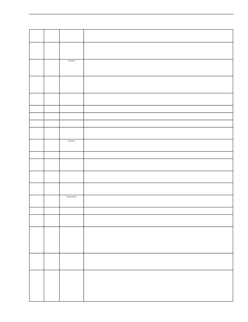
RSP
Receive Sync Pulse (CMOS Output).
This is an 8kHz 488ns active high framing
pulse, which marks the end of an ST-BUS frame. This is typically used for
connection to the Siemens MUNICH-32 device. See Figure 21.
13
7
F0o
Frame Pulse ST-BUS 2.048Mb/s (CMOS Output).
This is an 8kHz 244ns active
low framing pulse, which marks the beginning of an ST-BUS frame. This is typically
used for ST-BUS operation at 2.048Mb/s and 4.096Mb/s. See Figure 20.
14
8
TSP
Transmit Sync Pulse (CMOS Output).
This is an 8kHz 488ns active high framing
pulse, which marks the beginning of an ST-BUS frame. This is typically used for
connection to the Siemens MUNICH-32 device. See Figure 21.
15
9
F8o
Frame Pulse (CMOS Output).
This is an 8kHz 122ns active high framing pulse,
which marks the beginning of a frame. See Figure 20.
16
10
C1.5o
Clock 1.544MHz (CMOS Output).
This output is used in T1 applications.
17
11
AVDD
Analog Vdd.
+5V
DC
nominal.
Clock 3.088MHz (CMOS Output).
This output is used in T1 applications.
18
12
C3o
19
13
C2o
Clock 2.048MHz (CMOS Output).
This output is used for ST-BUS operation at
2.048Mb/s.
20
14
C4o
Clock 4.096MHz (CMOS Output).
This output is used for ST-BUS operation at
2.048Mb/s and 4.096Mb/s.
21
15
C19o
Clock 19.44MHz (CMOS Output).
This output is used in OC3/STS3 applications.
22
16
ACKi
Analog PLL Clock Input (CMOS Input).
This input clock is a reference for an
internal analog PLL. This pin is internally pulled down to VSS.
24
18
ACKo
Analog PLL Clock Output (CMOS Output).
This output clock is generated by
the internal analog PLL.
25
19
C8o
Clock 8.192MHz (CMOS Output).
This output is used for ST-BUS operation at
8.192Mb/s.
26
20
C16o
Clock 16.384MHz (CMOS Output).
This output is used for ST-BUS operation with
a 16.384MHz clock.
27
21
C6o
Clock 6.312 Mhz (CMOS Output).
This output is used for DS2 applications.
29
23
HOLDOVER
Holdover (CMOS Output).
This output goes to a logic high whenever the digital
PLL goes into holdover mode.
30
24
GTi
Guard Time (Schmitt Input).
This input is used by the MT9044 state machine in
both Manual and Automatic modes. The signal at this pin affects the state changes
between Primary Holdover Mode and Primary Normal Mode, and Primary
Holdover Mode and Secondary Normal Mode. The logic level at this input is gated
in by the rising edge of F8o. See Tables 4 and 5.
32
26
GTo
Guard Time (CMOS Output).
The LOS1 input is gated by the rising edge of F8o,
buffered and output on GTo. This pin is typically used to drive the GTi input through
an RC circuit.
33
27
LOS2
Secondary Reference Loss (TTL Input).
This input is normally connected to the
loss of signal (LOS) output signal of a Line Interface Unit (LIU). When high, the
SEC reference signal is lost or invalid. LOS2, along with the LOS1 and GTi inputs
control the MT9044 state machine when operating in Automatic Control. The logic
level at this input is gated in by the rising edge of F8o. This pin is internally pulled
down to VSS.
Pin Description (continued)
Pin #
PLCC
Pin #
MQFP
Name
Description
相關PDF資料 |
PDF描述 |
|---|---|
| MT90500 | Multi-Channel ATM AAL1 SAR(多通道 ATM AAL1分段及重組設備(基于通訊總線的系統(tǒng)與ATM網絡的接口)) |
| MT90500 | Multi-Channel ATM AAL1 SAR |
| MT90500AL | Multi-Channel ATM AAL1 SAR |
| MT90502 | Multi-Channel AAL2 SAR(多通道 ATM AAL2分段及重組設備(基于通訊總線的系統(tǒng)與ATM網絡的接口)) |
| MT90732AP | Ultraframer DS3/E3/DS2/E2/DS1/E1/DS0 |
相關代理商/技術參數 |
參數描述 |
|---|---|
| MT9044AL | 制造商:Microsemi Corporation 功能描述:FRAMER E1/OC3/T1 5V 44MQFP - Trays 制造商:Zarlink Semiconductor Inc 功能描述:FRAMER E1/OC3/T1 5V 44MQFP - Trays |
| MT9044AL1 | 制造商:Microsemi Corporation 功能描述:FRAMER E1/OC3/T1 5V 44MQFP - Trays |
| MT9044AP | 制造商:Microsemi Corporation 功能描述: |
| MT9044AP1 | 制造商:Microsemi Corporation 功能描述:FRAMER E1/OC3/T1 5V 44PLCC - Rail/Tube 制造商:Microsemi Corporation 功能描述:T1/E1/OC3 SYSTEM SYNCHRONIZER 制造商:MICROSEMI CONSUMER MEDICAL PRODUCT GROUP 功能描述:IC SYNCHRONIZER T1/E1 44PLCC 制造商:Microsemi Corporation 功能描述:IC SYNCHRONIZER T1/E1 44PLCC |
| MT9044APR1 | 制造商:Microsemi Corporation 功能描述:FRAMER E1/OC3/T1 5V 44PLCC - Tape and Reel 制造商:Zarlink Semiconductor Inc 功能描述:FRAMER E1/OC3/T1 5V 44PLCC - Tape and Reel |
發(fā)布緊急采購,3分鐘左右您將得到回復。