- 您現(xiàn)在的位置:買賣IC網(wǎng) > PDF目錄68019 > MTA85802S-10I/SS 8-BIT, OTPROM, 10 MHz, RISC MICROCONTROLLER, PDSO20 PDF資料下載
參數(shù)資料
| 型號(hào): | MTA85802S-10I/SS |
| 元件分類: | 微控制器/微處理器 |
| 英文描述: | 8-BIT, OTPROM, 10 MHz, RISC MICROCONTROLLER, PDSO20 |
| 封裝: | 0.209 INCH, PLASTIC, SSOP-20 |
| 文件頁數(shù): | 18/72頁 |
| 文件大小: | 760K |
| 代理商: | MTA85802S-10I/SS |
第1頁第2頁第3頁第4頁第5頁第6頁第7頁第8頁第9頁第10頁第11頁第12頁第13頁第14頁第15頁第16頁第17頁當(dāng)前第18頁第19頁第20頁第21頁第22頁第23頁第24頁第25頁第26頁第27頁第28頁第29頁第30頁第31頁第32頁第33頁第34頁第35頁第36頁第37頁第38頁第39頁第40頁第41頁第42頁第43頁第44頁第45頁第46頁第47頁第48頁第49頁第50頁第51頁第52頁第53頁第54頁第55頁第56頁第57頁第58頁第59頁第60頁第61頁第62頁第63頁第64頁第65頁第66頁第67頁第68頁第69頁第70頁第71頁第72頁
1995 Microchip Technology Inc.
DS40115C-page 25
MTA85XXX
11.1
External Crystal Oscillator circuit
A prepackaged oscillator can be used or a simple
oscillator circuit with TTL gates can be built. Prepack-
aged oscillators provide a wide operating range and
better stability. A well-designed crystal oscillator will
provide good performance with TTL gates. Two types
of crystal oscillator circuits can be used; one with series
resonance, or one with parallel resonance.
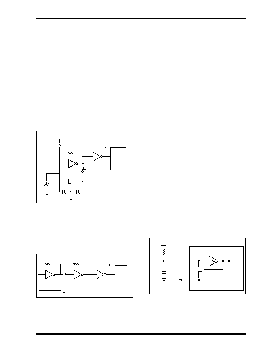
Figure 11-3
shows
implementation
of
a
parallel
resonant oscillator circuit. The circuit is designed to use
the fundamental frequency of the crystal. The 74AS04
inverter performs the 180-degree phase shift that a par-
allel oscillator requires. The 4.7 k
resistor provides
the negative feedback for stability. The 10 k
potenti-
ometers bias the 74AS04 in the linear region. This cir-
cuit could be used for external oscillator designs.
FIGURE 11-3: EXTERNAL PARALLEL
RESONANT CRYSTAL
OSCILLATOR CIRCUIT
Figure 11-4 shows a series resonant oscillator circuit.
This circuit is also designed to use the fundamental
frequency of the crystal. The inverter performs a 180
°
phase shift in a series resonant oscillator circuit. The
330
resistors provide the negative feedback to bias
the inverters in their linear region.
FIGURE 11-4: EXTERNAL SERIES
RESONANT CRYSTAL
OSCILLATOR CIRCUIT
20 pF
+5V
20 pF
10k
4.7k
10k
74AS04
XTAL
10k
74AS04
PIC16C5X
CLKIN
To Other
Devices
330
74AS04
PIC16C5X
CLKIN
To Other
Devices
XTAL
330
74AS04
0.1
F
11.1.1
RC OSCILLATOR
For timing insensitive applications the RC device option
offers additional cost savings. RC oscillator frequency
is a function of the supply voltage, the resistor (Rext)
and capacitor (Cext) values, and the operating temper-
ature. In addition to this, the oscillator frequency will
vary from unit to unit due to normal process parameter
variation. Furthermore, the difference in lead frame
capacitance between package types will also affect the
oscillation frequency, especially for low Cext values.
The user also needs to take into account variation due
to tolerance of external R and C components used.
Figure 11-5 shows how the R/C combination is con-
nected to the PIC16C5X. For Rext values below 2.2
k
, the oscillator operation may become unstable, or
stop completely. For very high Rext values (e.g., 1 M
)
the oscillator becomes sensitive to noise, humidity and
leakage. Thus, we recommend keeping Rext between
3k
and 100 k.
Although the oscillator will operate with no external
capacitor (Cext = 0 pF), we recommend using values
above 20 pF for noise and stability reasons. With no or
small external capacitance, the oscillation frequency
can vary dramatically due to changes in external
capacitances, such as PCB trace capacitance or pack-
age lead frame capacitance.
See Section 15.0 for RC frequency variation from part
to part due to normal process variation. The variation is
larger for larger R (since leakage current variation will
affect RC frequency more for large R) and for smaller
C (since variation of input capacitance will affect RC
frequency more).
See Section 15.0 for variation of oscillator frequency
due to VDD for given Rext/Cext values as well as
frequency variation due to operating temperature for
given R, C, and VDD values.
The oscillator frequency, divided by 4, is available on
the OSC2/CLKOUT pin, and can be used for test
purposes or to synchronize other logic.
FIGURE 11-5: RC OSCILLATOR MODE
VDD
Rext
Cext
VSS
OSC1
Internal
clock
OSC2/CLKOUT
Fosc/4
PIC16C5X
N
相關(guān)PDF資料 |
PDF描述 |
|---|---|
| MTA85811-04I/SS | 8-BIT, OTPROM, 4 MHz, RISC MICROCONTROLLER, PDSO20 |
| MTA85802-10I/SS | 8-BIT, OTPROM, 10 MHz, RISC MICROCONTROLLER, PDSO20 |
| MTA85801-10I/SS | 8-BIT, OTPROM, 10 MHz, RISC MICROCONTROLLER, PDSO20 |
| MTA85812-10I/SS | 8-BIT, OTPROM, 10 MHz, RISC MICROCONTROLLER, PDSO20 |
| MTA85402S-04I/SS | 8-BIT, OTPROM, 4 MHz, RISC MICROCONTROLLER, PDSO20 |
相關(guān)代理商/技術(shù)參數(shù) |
參數(shù)描述 |
|---|---|
| MTA8808 | 制造商:Pulse Electronics Corporation 功能描述: |
| MTA8ATF1G64AZ-2G3B1 | 功能描述:Memory Module DDR4 SDRAM 8GB 2400MT/s 288-UDIMM 制造商:micron technology inc. 系列:- 零件狀態(tài):在售 存儲(chǔ)器類型:DDR4 SDRAM 存儲(chǔ)容量:8GB 速度:2400MT/s 封裝/外殼:288-UDIMM 標(biāo)準(zhǔn)包裝:1 |
| MTA8ATF1G64HZ-2G3B1 | 功能描述:Memory Module DDR4 SDRAM 8GB 2400MT/s 260-SODIMM 制造商:micron technology inc. 系列:- 零件狀態(tài):在售 存儲(chǔ)器類型:DDR4 SDRAM 存儲(chǔ)容量:8GB 速度:2400MT/s 封裝/外殼:260-SODIMM 標(biāo)準(zhǔn)包裝:1 |
| MTA8D50 | 制造商:Mallory Sonalert Products Inc 功能描述:Molded Tubular Aluminum Electrolytic Axial Leads Capacitor - 8uF 50dcV -10+100% |
| MTA90A | 制造商:LIUJING 制造商全稱:LIUJING 功能描述:可控硅(晶閘管) |
發(fā)布緊急采購,3分鐘左右您將得到回復(fù)。