- 您現(xiàn)在的位置:買賣IC網(wǎng) > PDF目錄367733 > P83CL781HDH (NXP SEMICONDUCTORS) Low voltage 8-bit microcontrollers with UART and I2C-bus PDF資料下載
參數(shù)資料
| 型號: | P83CL781HDH |
| 廠商: | NXP SEMICONDUCTORS |
| 元件分類: | 微控制器/微處理器 |
| 英文描述: | Low voltage 8-bit microcontrollers with UART and I2C-bus |
| 中文描述: | 8-BIT, MROM, 12 MHz, MICROCONTROLLER, PQFP44 |
| 封裝: | 10 X 10 MM, 1.75 MM HEIGHT, PLASTIC, SOT-307-2, QFP-44 |
| 文件頁數(shù): | 61/76頁 |
| 文件大?。?/td> | 342K |
| 代理商: | P83CL781HDH |
第1頁第2頁第3頁第4頁第5頁第6頁第7頁第8頁第9頁第10頁第11頁第12頁第13頁第14頁第15頁第16頁第17頁第18頁第19頁第20頁第21頁第22頁第23頁第24頁第25頁第26頁第27頁第28頁第29頁第30頁第31頁第32頁第33頁第34頁第35頁第36頁第37頁第38頁第39頁第40頁第41頁第42頁第43頁第44頁第45頁第46頁第47頁第48頁第49頁第50頁第51頁第52頁第53頁第54頁第55頁第56頁第57頁第58頁第59頁第60頁當(dāng)前第61頁第62頁第63頁第64頁第65頁第66頁第67頁第68頁第69頁第70頁第71頁第72頁第73頁第74頁第75頁第76頁

1997 Mar 14
61
Philips Semiconductors
Product specification
Low voltage 8-bit microcontrollers with
UART and I
2
C-bus
P83CL781; P83CL782
Notes
1.
Capacitive loading on Ports 0 and 2 may cause spurious noise pulses to be superimposed on the LOW level output
voltage of ALE, Port 1 and Port 3 pins when these make a HIGH-to-LOW transition during bus operations. The noise
is due to external bus capacitance discharging into the Port 0 and Port 2 pins when these pins make HIGH-to-LOW
transitions during bus operations. In the most adverse conditions (capacitive loading
>
100 pF), the noise pulse on
the ALE line may exceed 0.8 V. In such events it may be required to qualify ALE with a Schmitt trigger, or use an
address latch with a Schmitt trigger strobe input.
Capacitive loading on Ports 0 and 2 may cause the HIGH level output voltage on ALE and PSEN to momentarily fall
below the 0.9% of V
DD
specification when the address bits are stabilizing.
Circuits with Power-on reset option ‘OFF’ are tested at V
DDmin
= 1.8 V; with the ‘ON’ option (typically 1.3 V) they are
tested at V
DDmin
= 2.3 V.
The operating supply current is measured with all output pins disconnected; XTAL1 driven with t
r
= t
f
=10 ns;
V
IL
= V
SS
; V
IH
= V
DD
; XTAL2 not connected; EA = RST = Port 0 = V
DD
.
The Idle mode supply current is measured with all output pins disconnected; XTAL1 driven with t
r
= t
f
= 10 ns;
V
IL
= V
SS
; V
IH
= V
DD
; XTAL2 not connected; EA = Port 0 = V
DD
.
The Power-down current is measured with all output pins disconnected; XTAL1 not connected; EA = Port 0 = V
DD
;
RST = V
SS
.
The input threshold voltage of P1.6/SCL and P1.7/SDA meet the I
2
C-bus specification. Therefore, an input voltage
below 0.3V
DD
will be recognized as a logic 0 and an input voltage above 0.7V
DD
will be recognized as a logic 1.
2.
3.
4.
5.
6.
7.
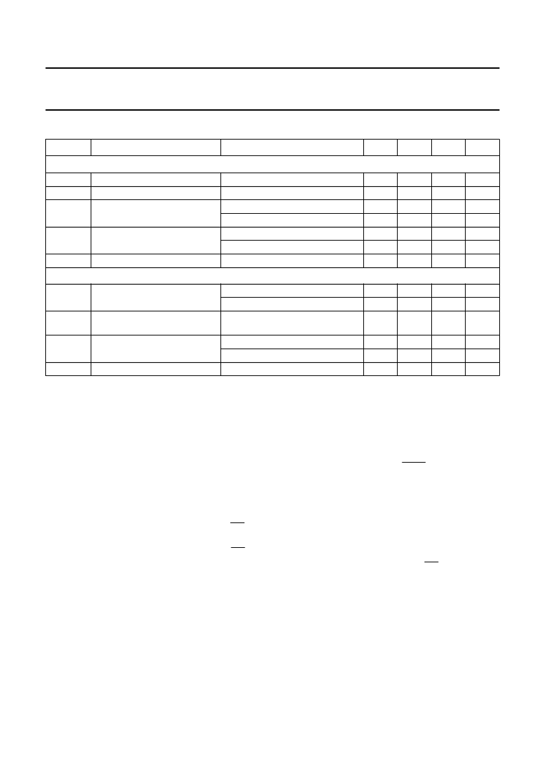
Inputs
V
IL
V
IH
I
IL
LOW level input voltage
HIGH level input voltage
LOW level input current
note 7
note 7
V
DD
= 5 V; V
IN
= 0.4 V; note 7
V
DD
= 2.5 V; V
IN
= 0.4 V; note 7
V
DD
= 5 V; V
IN
= 0.5V
DD
; note 7
V
DD
= 2.5 V; V
IN
= 0.5V
DD
; note 7
V
SS
<
V
I
<
V
DD
; note 7
V
SS
0.7V
DD
0.3V
DD
V
V
DD
100
50
1.0
500
±
10
V
μ
A
μ
A
mA
μ
A
μ
A
I
IL(T)
LOW level input current
(HIGH-to-LOW transition)
I
LI
Outputs
input leakage current
I
OL
LOW level output current;
except SDA and SCL
V
DD
= 5 V; V
OL
= 0.4 V
V
DD
= 2.5 V; V
OL
= 0.4 V
V
DD
= 5 V; V
OL
= 0.4 V
1.6
0.7
3.0
mA
mA
mA
I
OL1
LOW level output current; SDA
and SCL
HIGH level output current
(push-pull options only)
I
OH
V
DD
= 5 V; V
OH
= V
DD
0.4 V
V
DD
= 2.5 V; V
OH
= V
DD
0.4 V
1.6
0.7
10
200
mA
mA
k
R
RST
RST pull-down resistor
SYMBOL
PARAMETER
CONDITIONS
MIN.
TYP.
MAX.
UNIT
相關(guān)PDF資料 |
PDF描述 |
|---|---|
| P83CL882 | 80C51 Ultra Low Power ULP telephony controller |
| P83CL883T | TELX microcontrollers for CT0 handset/basestation applications |
| P83CL884T | TELX microcontrollers for CT0 handset/basestation applications |
| P87CL883T | TELX microcontrollers for CT0 handset/basestation applications |
| P87CL884T | TELX microcontrollers for CT0 handset/basestation applications |
相關(guān)代理商/技術(shù)參數(shù) |
參數(shù)描述 |
|---|---|
| P83CL781HFB | 制造商:未知廠家 制造商全稱:未知廠家 功能描述:8-Bit Microcontroller |
| P83CL781HFH | 制造商:PHILIPS 制造商全稱:NXP Semiconductors 功能描述:Low voltage 8-bit microcontrollers with UART and I2C-bus |
| P83CL781HFN | 制造商:未知廠家 制造商全稱:未知廠家 功能描述:8-Bit Microcontroller |
| P83CL781HFP | 制造商:PHILIPS 制造商全稱:NXP Semiconductors 功能描述:Low voltage 8-bit microcontrollers with UART and I2C-bus |
| P83CL782 | 制造商:PHILIPS 制造商全稱:NXP Semiconductors 功能描述:Low voltage 8-bit microcontrollers with UART and I2C-bus |
發(fā)布緊急采購,3分鐘左右您將得到回復(fù)。