- 您現(xiàn)在的位置:買賣IC網(wǎng) > PDF目錄367738 > P87C552 (NXP Semiconductors N.V.) 80C51 8-bit microcontroller(80C51八位微控制器) PDF資料下載
參數(shù)資料
| 型號(hào): | P87C552 |
| 廠商: | NXP Semiconductors N.V. |
| 英文描述: | 80C51 8-bit microcontroller(80C51八位微控制器) |
| 中文描述: | 80C51的8位微控制器(80C51的八位微控制器) |
| 文件頁數(shù): | 23/74頁 |
| 文件大?。?/td> | 368K |
| 代理商: | P87C552 |
第1頁第2頁第3頁第4頁第5頁第6頁第7頁第8頁第9頁第10頁第11頁第12頁第13頁第14頁第15頁第16頁第17頁第18頁第19頁第20頁第21頁第22頁當(dāng)前第23頁第24頁第25頁第26頁第27頁第28頁第29頁第30頁第31頁第32頁第33頁第34頁第35頁第36頁第37頁第38頁第39頁第40頁第41頁第42頁第43頁第44頁第45頁第46頁第47頁第48頁第49頁第50頁第51頁第52頁第53頁第54頁第55頁第56頁第57頁第58頁第59頁第60頁第61頁第62頁第63頁第64頁第65頁第66頁第67頁第68頁第69頁第70頁第71頁第72頁第73頁第74頁
Philips Semiconductors
Preliminary specification
P87C552
80C51 8-bit microcontroller
8K/256 OTP, 8 channel 10 bit A/D, I
2
C, PWM,
capture/compare, high I/O, low voltage (2.7V–5.5V), low power
1999 Mar 30
23
SUCCESSIVE
APPROXIMATION
CONTROL LOGIC
SUCCESSIVE
APPROXIMATION
REGISTER
DAC
+
–
START
STOP
V
in
V
DAC
0
1
2
3
4
5
6
t/tau
V
DAC
FULL SCALE
1
V
in
1/2
3/4
7/8
15/16
29/32
59/64
SU00958
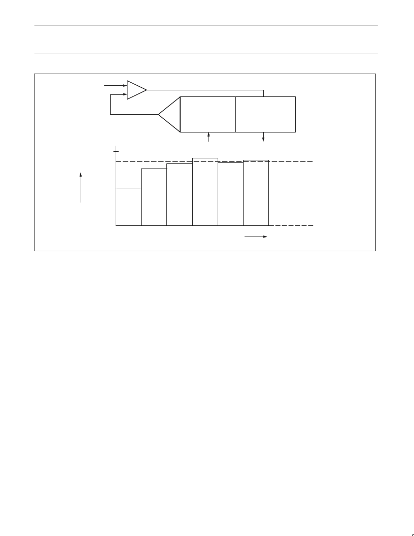
Figure 20. Successive Approximation ADC
The low-to-high transition of STADC is recognized at the end of a
machine cycle, and the conversion commences at the beginning of
the next cycle. When a conversion is initiated by software, the
conversion starts at the beginning of the machine cycle which
follows the instruction that sets ADCS. ADCS is actually
implemented with two flip-flops: a command flip-flop which is
affected by set operations, and a status flag which is accessed
during read operations.
The next two machine cycles are used to initiate the converter. At
the end of the first cycle, the ADCS status flag is set and a value of
“1” will be returned if the ADCS flag is read while the conversion is in
progress. Sampling of the analog input commences at the end of the
second cycle.
During the next eight machine cycles, the voltage at the previously
selected pin of port 5 is sampled, and this input voltage should be
stable in order to obtain a useful sample. In any event, the input
voltage slew rate must be less than 10V/ms in order to prevent an
undefined result.
The successive approximation control logic first sets the most
significant bit and clears all other bits in the successive
approximation register (10 0000 0000B). The output of the DAC
(50% full scale) is compared to the input voltage Vin. If the input
voltage is greater than VDAC, then the bit remains set; otherwise it
is cleared.
The successive approximation control logic now sets the next most
significant bit (11 0000 0000B or 01 0000 0000B, depending on the
previous result), and VDAC is compared to Vin again. If the input
voltage is greater than VDAC, then the bit being tested remains set;
otherwise the bit being tested is cleared. This process is repeated
until all ten bits have been tested, at which stage the result of the
conversion is held in the successive approximation register.
Figure 21 shows a conversion flow chart. The bit pointer identifies
the bit under test. The conversion takes four machine cycles per bit.
The end of the 10-bit conversion is flagged by control bit ADCON.4
(ADCI). The upper 8 bits of the result are held in special function
register ADCH, and the two remaining bits are held in ADCON.7
(ADC.1) and ADCON.6 (ADC.0). The user may ignore the two least
significant bits in ADCON and use the ADC as an 8-bit converter (8
upper bits in ADCH). In any event, the total actual conversion time is
50 machine cycles for the 8XC552. ADCI will be set and the ADCS
status flag will be reset 50 (or 24) cycles after the command flip-flop
(ADCS) is set.
Control bits ADCON.0, ADCON.1, and ADCON.2 are used to control
an analog multiplexer which selects one of eight analog channels
(see Figure 22). An ADC conversion in progress is unaffected by an
external or software ADC start. The result of a completed
conversion remains unaffected provided ADCI = logic 1; a new ADC
conversion already in progress is aborted when the idle or
power-down mode is entered. The result of a completed conversion
(ADCI = logic 1) remains unaffected when entering the idle mode.
相關(guān)PDF資料 |
PDF描述 |
|---|---|
| P87C554SBBD | 80C51 8-bit microcontroller . 6 clock operation 16K/512 OTP/ROM/ROMless, 7 channel 10 bit A/D, I2C, PWM, capture/compare, high I/O, 64L LQFP |
| P83C554SBBD | 80C51 8-bit microcontroller . 6 clock operation 16K/512 OTP/ROM/ROMless, 7 channel 10 bit A/D, I2C, PWM, capture/compare, high I/O, 64L LQFP |
| P80C554SBBD | 80C51 8-bit microcontroller . 6 clock operation 16K/512 OTP/ROM/ROMless, 7 channel 10 bit A/D, I2C, PWM, capture/compare, high I/O, 64L LQFP |
| P87C554SFBD | 80C51 8-bit microcontroller . 6 clock operation 16K/512 OTP/ROM/ROMless, 7 channel 10 bit A/D, I2C, PWM, capture/compare, high I/O, 64L LQFP |
| P83C554SFBD | 80C51 8-bit microcontroller . 6 clock operation 16K/512 OTP/ROM/ROMless, 7 channel 10 bit A/D, I2C, PWM, capture/compare, high I/O, 64L LQFP |
相關(guān)代理商/技術(shù)參數(shù) |
參數(shù)描述 |
|---|---|
| P87C552OTP | 制造商:PHILIPS 制造商全稱:NXP Semiconductors 功能描述:80C51 8-bit microcontroller |
| P87C552SBAA | 制造商:NXP Semiconductors 功能描述:87C 16MHz 制造商:NXP Semiconductors 功能描述:87C 16MHz Bulk 制造商:NXP Semiconductors 功能描述:IC 8-BIT MCU 8K OTP PLCC68 制造商:NXP Semiconductors 功能描述:MCU 8-Bit 87C 80C51 CISC 8KB EPROM 3.3V/5V 68-Pin PLCC |
| P87C552SBAA,512 | 功能描述:8位微控制器 -MCU 80C51 8K/256 OTP RoHS:否 制造商:Silicon Labs 核心:8051 處理器系列:C8051F39x 數(shù)據(jù)總線寬度:8 bit 最大時(shí)鐘頻率:50 MHz 程序存儲(chǔ)器大小:16 KB 數(shù)據(jù) RAM 大小:1 KB 片上 ADC:Yes 工作電源電壓:1.8 V to 3.6 V 工作溫度范圍:- 40 C to + 105 C 封裝 / 箱體:QFN-20 安裝風(fēng)格:SMD/SMT |
| P87C552SBAA512 | 制造商:NXP Semiconductors 功能描述:IC 8BIT MCU 80C51 16MHZ LCC-68 |
| P87C552SFAA | 制造商:NXP Semiconductors 功能描述:IC 8BIT MCU SMD 87C552 PLCC68 |
發(fā)布緊急采購,3分鐘左右您將得到回復(fù)。