- 您現(xiàn)在的位置:買賣IC網(wǎng) > PDF目錄369945 > P90CE201 (NXP Semiconductors N.V.) 16-bit microcontroller PDF資料下載
參數(shù)資料
| 型號(hào): | P90CE201 |
| 廠商: | NXP Semiconductors N.V. |
| 英文描述: | 16-bit microcontroller |
| 中文描述: | 16位微控制器 |
| 文件頁(yè)數(shù): | 58/77頁(yè) |
| 文件大小: | 235K |
| 代理商: | P90CE201 |
第1頁(yè)第2頁(yè)第3頁(yè)第4頁(yè)第5頁(yè)第6頁(yè)第7頁(yè)第8頁(yè)第9頁(yè)第10頁(yè)第11頁(yè)第12頁(yè)第13頁(yè)第14頁(yè)第15頁(yè)第16頁(yè)第17頁(yè)第18頁(yè)第19頁(yè)第20頁(yè)第21頁(yè)第22頁(yè)第23頁(yè)第24頁(yè)第25頁(yè)第26頁(yè)第27頁(yè)第28頁(yè)第29頁(yè)第30頁(yè)第31頁(yè)第32頁(yè)第33頁(yè)第34頁(yè)第35頁(yè)第36頁(yè)第37頁(yè)第38頁(yè)第39頁(yè)第40頁(yè)第41頁(yè)第42頁(yè)第43頁(yè)第44頁(yè)第45頁(yè)第46頁(yè)第47頁(yè)第48頁(yè)第49頁(yè)第50頁(yè)第51頁(yè)第52頁(yè)第53頁(yè)第54頁(yè)第55頁(yè)第56頁(yè)第57頁(yè)當(dāng)前第58頁(yè)第59頁(yè)第60頁(yè)第61頁(yè)第62頁(yè)第63頁(yè)第64頁(yè)第65頁(yè)第66頁(yè)第67頁(yè)第68頁(yè)第69頁(yè)第70頁(yè)第71頁(yè)第72頁(yè)第73頁(yè)第74頁(yè)第75頁(yè)第76頁(yè)第77頁(yè)

August 1993
58
Philips Semiconductors
Product specification
16-bit microcontroller
P90CE201
13.3
Timer registers
13.3.1
T
IMER
C
ONTROL
R
EGISTER
(TnCON)
The Timer Control Register (TnCON) controls the selection of the timer operating modes and the UART clock source.
Table 48
Description of TnCON bits.
SYMBOL
BIT
FUNCTION
TFn
TnCON.7
Timer n overflow flag. Set by a Timer n overflow and must be cleared by software.
TFn will not be set when either RCLKn = 1 or TCLKn = 1.
Timer n external flag. Set when either a capture or reload is caused by a negative
transition on external input Tn and when EXENn = 1. EXFn must be cleared by
software.
Receive Clock flag. When set, causes the UART to use Timer n overflow pulses
for its receive clock in Modes 1 and 3. See Table 50.
Transmit Clock flag. When set, causes the UART to use Timer n overflow pulses
for its transmit clock in Modes 1 and 3. See Table 50.
Timer n external enable flag. When set, allows a capture or reload to occur as a
result of a negative transition on external input Tn, if Timer n is not being used to
clock the UART. EXENn = 0 causes Timer 2 to ignore events at external input Tn.
Start/Stop control. TRn = 1 starts Timer n; TRn = 0 stops the timer.
Timer or Counter select. C/Tn = 0 selects the internal timer. C/Tn = 1 selects the
external event counter (edge triggered).
Capture/Reload flag. When set, captures will occur on valid transitions at external
input Tn, if EXEn2 = 1. When cleared, auto-reloads will occur upon either Timer n
overflows or valid transitions at Tn, if EXENn = 1. When either RCLKn = 1 or
TCLKn = 1, this bit is ignored and the timer is forced to auto-reload on a Timer n
overflow.
EXFn
TnCON.6
RCLKn
TnCON.5
TCLKn
TnCON.4
EXENn
TnCON.3
TRn
C/Tn
TnCON.2
TnCON.1
CP/RLn
TnCON.0
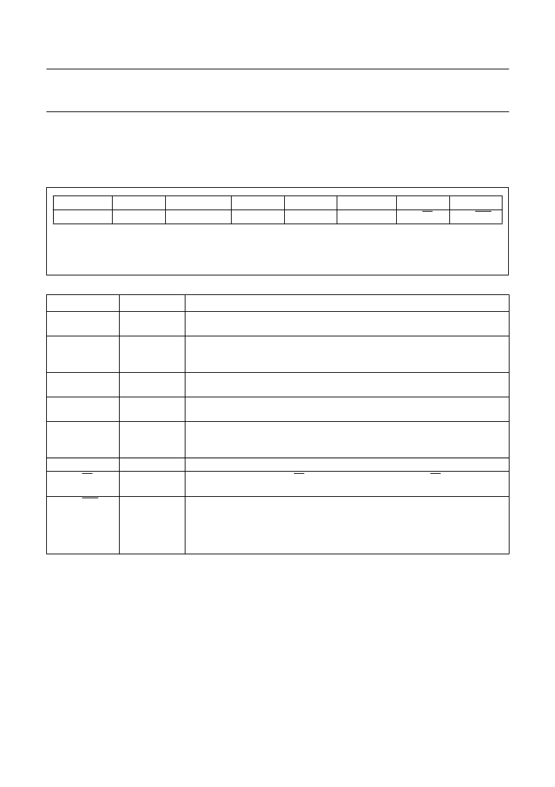
Fig.43 Timer Control Registers (TnCON).
bit 7
TFn
bit 6
EXFn
bit 5
RCLKn
bit 4
TCLKn
bit 3
EXENn
bit 2
TRn
bit 1
C/Tn
bit 0
CP/RLn
相關(guān)PDF資料 |
PDF描述 |
|---|---|
| P90CE201AEB | 16-bit microcontroller |
| P9217 | PbS photoconductive detector |
| P930 | CdS photoconductive cell |
| PA025XSB | This technical specification applies to 2.5inch color TFT-LCD panel. |
| PA025XSC | This technical specification applies to 2.5inch color TFT-LCD panel. |
相關(guān)代理商/技術(shù)參數(shù) |
參數(shù)描述 |
|---|---|
| P90CE201AEB | 制造商:PHILIPS 制造商全稱:NXP Semiconductors 功能描述:16-bit microcontroller |
| P90CL301 | 制造商:PHILIPS 制造商全稱:NXP Semiconductors 功能描述:Low voltage 16-bit microcontroller |
| P90CL301BFH | 制造商:PHILIPS 制造商全稱:NXP Semiconductors 功能描述:Low voltage 16-bit microcontroller |
| P-90-F | 制造商:Hozan Tool Industrial Co Ltd 功能描述: |
| P90PCT101PC | 制造商:PERFORMANCE/ 功能描述:90PCT101PC |
發(fā)布緊急采購(gòu),3分鐘左右您將得到回復(fù)。