- 您現(xiàn)在的位置:買賣IC網(wǎng) > PDF目錄378045 > PCA9544ARGWR (Texas Instruments, Inc.) 4-CHANNEL IC AND SMBus MULTIPLEXER WITH INTERRUPT LOGIC PDF資料下載
參數(shù)資料
| 型號: | PCA9544ARGWR |
| 廠商: | Texas Instruments, Inc. |
| 英文描述: | 4-CHANNEL IC AND SMBus MULTIPLEXER WITH INTERRUPT LOGIC |
| 中文描述: | 4通道多路轉(zhuǎn)換集成電路和SMBus與中斷邏輯 |
| 文件頁數(shù): | 1/23頁 |
| 文件大?。?/td> | 578K |
| 代理商: | PCA9544ARGWR |
www.ti.com
FEATURES
DESCRIPTION/ORDERING INFORMATION
The PCA9544A is a quad bidirectional translating switch controlled via the I
2
C bus. The SCL/SDA upstream pair
fans out to four downstream pairs, or channels. One SCL/SDA pair can be selected at a time, and this is
determined by the contents of the programmable control register. Four interrupt inputs (INT3–INT0), one for each
of the downstream pairs, are provided. One interrupt output (INT) acts as an AND of the four interrupt inputs.
A power-on reset function puts the registers in their default state and initializes the I
2
C state machine, with no
channel selected.
PCA9544A
4-CHANNEL I
2
C AND SMBus MULTIPLEXER
WITH INTERRUPT LOGIC
SCPS146A–OCTOBER 2005–REVISED OCTOBER 2005
1-of-4 Bidirectional Translating Switches
I
2
C Bus and SMBus Compatible
Four Active-Low Interrupt Inputs
Active-Low Interrupt Output
Three Address Pins, Allowing up to Eight
Devices on the I
2
C Bus
Channel Selection Via I
2
C Bus
Power Up With All Switch Channels
Deselected
Low R
ON
Switches
Allows Voltage-Level Translation Between
1.8-V, 2.5-V, 3.3-V, and 5-V Buses
No Glitch on Power Up
Supports Hot Insertion
Low Standby Current
Operating Power-Supply Voltage Range of
2.3 V to 5.5 V
5.5-V Tolerant Inputs
0 to 400-kHz Clock Frequency
Latch-Up Performance Exceeds 100 mA Per
JESD 78
ESD Protection Exceeds JESD 22
– 2000-V Human-Body Model (A114-A)
– 200-V Machine Model (A115-A)
– 1000-V Charged-Device Model (C101)
The pass gates of the switches are constructed such that the V
CC
pin can be used to limit the maximum high
voltage, which will be passed by the PCA9544A. This allows the use of different bus voltages on each pair, so
that 1.8-V, 2.5-V, or 3.3-V parts can communicate with 5-V parts, without any additional protection. External
pullup resistors pull the bus up to the desired voltage level for each channel. All I/O pins are 5-V tolerant.
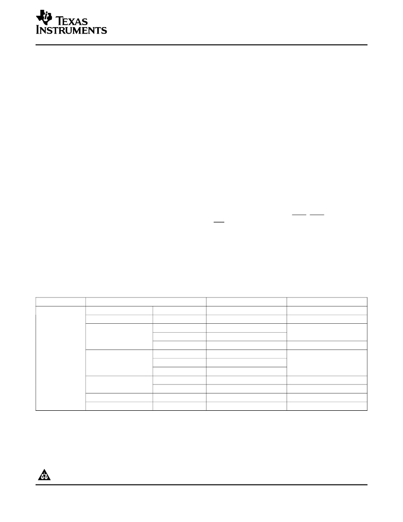
ORDERING INFORMATION
T
A
PACKAGE
(1)
ORDERABLE PART NUMBER
PCA9544ARGWR
PCA9544ARGYR
PCA9544ADW
PCA9544ADWR
PCA9544ADWT
PCA9544APW
PCA9544APWR
PCA9544APWT
PCA9544ADGVR
PCA9544ADGVT
PCA9544AGQNR
PCA9544AZQNR
TOP-SIDE MARKING
PREVIEW
PD544A
QFN – RGW
QFN – RGY
Reel of 3000
Reel of 1000
Tube of 25
Reel of 2000
Reel of 250
Tube of 70
Reel of 2000
Reel of 250
Reel of 2000
Reel of 250
Reel of 1000
Reel of 1000
PCA9544A
SOIC – DW
PREVIEW
–40
°
C to 85
°
C
TSSOP – PW
PD544A
PD544A
PREVIEW
PD544A
PD544A
TVSOP – DGV
VFBGA – GQN
VFBGA – ZQN (Pb-free)
(1)
Package drawings, standard packing quantities, thermal data, symbolization, and PCB design guidelines are available at
www.ti.com/sc/package.
Please be aware that an important notice concerning availability, standard warranty, and use in critical applications of Texas
Instruments semiconductor products and disclaimers thereto appears at the end of this data sheet.
PRODUCTION DATA information is current as of publication date.
Products conform to specifications per the terms of the Texas
Instruments standard warranty. Production processing does not
necessarily include testing of all parameters.
Copyright 2005, Texas Instruments Incorporated
相關(guān)PDF資料 |
PDF描述 |
|---|---|
| PCC | Programmable Capacitor Chips |
| PCC510-04OM | Programmable Capacitor Chips |
| PCC510-05OM | Programmable Capacitor Chips |
| PCI1221GHK | KPT 11C 11#16 SKT PLUG |
| PCI1410GHK | PC CARD CONTROLLERS |
相關(guān)代理商/技術(shù)參數(shù) |
參數(shù)描述 |
|---|---|
| PCA9544ARGYR | 功能描述:多路器開關(guān) IC 4-Ch I2C & SMBus Multiplexer RoHS:否 制造商:Texas Instruments 通道數(shù)量:1 開關(guān)數(shù)量:4 開啟電阻(最大值):7 Ohms 開啟時間(最大值): 關(guān)閉時間(最大值): 傳播延遲時間:0.25 ns 工作電源電壓:2.3 V to 3.6 V 工作電源電流: 最大工作溫度:+ 85 C 安裝風(fēng)格:SMD/SMT 封裝 / 箱體:UQFN-16 |
| PCA9544ARGYRG4 | 功能描述:多路器開關(guān) IC 4-Ch I2C & SMBus Multiplexer RoHS:否 制造商:Texas Instruments 通道數(shù)量:1 開關(guān)數(shù)量:4 開啟電阻(最大值):7 Ohms 開啟時間(最大值): 關(guān)閉時間(最大值): 傳播延遲時間:0.25 ns 工作電源電壓:2.3 V to 3.6 V 工作電源電流: 最大工作溫度:+ 85 C 安裝風(fēng)格:SMD/SMT 封裝 / 箱體:UQFN-16 |
| PCA9544AZQNR | 功能描述:多路器開關(guān) IC 4-Ch I2C & SMBus Multiplexer RoHS:否 制造商:Texas Instruments 通道數(shù)量:1 開關(guān)數(shù)量:4 開啟電阻(最大值):7 Ohms 開啟時間(最大值): 關(guān)閉時間(最大值): 傳播延遲時間:0.25 ns 工作電源電壓:2.3 V to 3.6 V 工作電源電流: 最大工作溫度:+ 85 C 安裝風(fēng)格:SMD/SMT 封裝 / 箱體:UQFN-16 |
| PCA9544D | 制造商:未知廠家 制造商全稱:未知廠家 功能描述:BUS CONTROLLER |
| PCA9544PW | 制造商:PHILIPS 制造商全稱:NXP Semiconductors 功能描述:4-channel I2C multiplexer and interrupt controller |
發(fā)布緊急采購,3分鐘左右您將得到回復(fù)。