- 您現(xiàn)在的位置:買(mǎi)賣(mài)IC網(wǎng) > PDF目錄69049 > PKD01BIEP (ANALOG DEVICES INC) SPECIALTY ANALOG CIRCUIT, PDIP14 PDF資料下載
參數(shù)資料
| 型號(hào): | PKD01BIEP |
| 廠商: | ANALOG DEVICES INC |
| 元件分類: | 模擬信號(hào)調(diào)理 |
| 英文描述: | SPECIALTY ANALOG CIRCUIT, PDIP14 |
| 封裝: | PLASTIC, DIP-14 |
| 文件頁(yè)數(shù): | 5/18頁(yè) |
| 文件大小: | 402K |
| 代理商: | PKD01BIEP |
第1頁(yè)第2頁(yè)第3頁(yè)第4頁(yè)當(dāng)前第5頁(yè)第6頁(yè)第7頁(yè)第8頁(yè)第9頁(yè)第10頁(yè)第11頁(yè)第12頁(yè)第13頁(yè)第14頁(yè)第15頁(yè)第16頁(yè)第17頁(yè)第18頁(yè)

REV. A
PKD01
–13–
PEAK HOLD CAPACITOR RECOMMENDATIONS
The hold capacitor (CH) serves as the peak memory element
and compensating capacitor. Stable operation requires a mini-
mum value of 1000 pF. Larger capacitors may be used to lower
droop rate errors, but acquisition time will increase.
Zero scale error is internally trimmed for CH = 1000 pF. Other
CH values will cause a zero scale shift which can be approxi-
mated with the following equation.
VmV
pC
CnF
mV
ZS
H
() =
×
()
110
06
3
.
The peak hold capacitor should have very high insulation resis-
tance and low dielectric absorption. For temperatures below
85
°C, a polystyrene capacitor is recommended, while a Teflon
capacitor is recommended for high temperature environments.
CAPACITOR GUARDING AND GROUND LAYOUT
Ground planes are recommended to minimize ground path
resistance. Separate analog and digital grounds should be used.
The two ground systems are tied together only at the common
system ground. This avoids digital currents returning to the
system ground through the analog ground path.
PKD01
CH
REPEAT ON
“COMPONENT SIDE”
OF PC BOARD IF POSSIBLE
BOTTOM VIEW
14
13
12
11
10
9
8
1
2
3
4
5
6
7
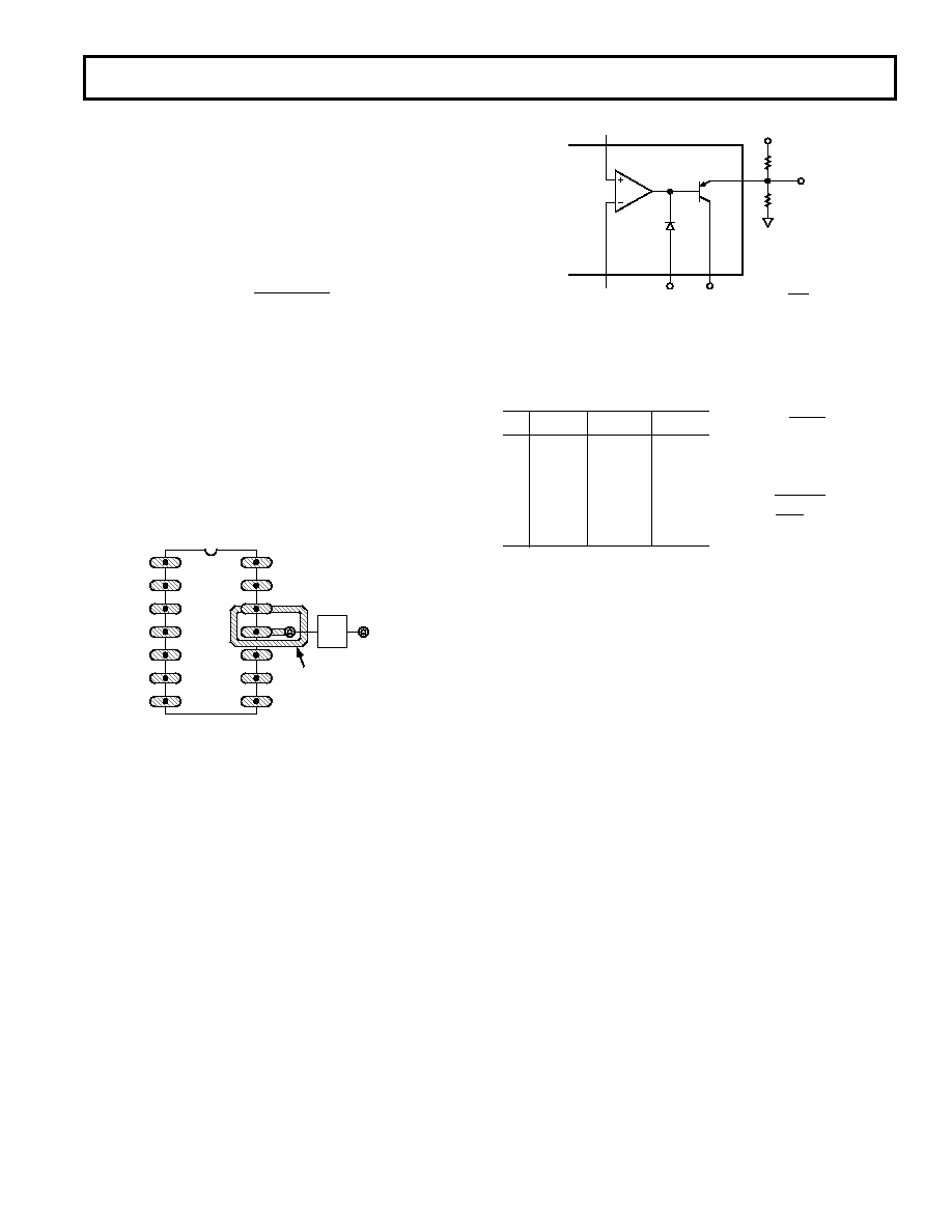
Figure 9. CH Terminal (Pin 4) Guarding. See Text.
The CH terminal (Pin 4) is a high impedance point. To minimize
gain errors and maintain the PKD01’s inherently low droop rate,
guarding Pin 4 as shown in Figure 9 is recommended.
COMPARATOR
The comparator output high level (VOH) is set by external resis-
tors. It is possible to optimize noise immunity while interfacing
to all standard logic families—TTL, DTL, and CMOS. Figure
10 shows the comparator output with external level-setting
resistors. Table I gives typical R1 and R2 values for common
circuit conditions.
The maximum comparator high output voltage (VOH) should be
limited to:
VOH (maximum) < V+ –2.0 V
With the comparator in the low state (VOL), the output stage
will be required to sink a current approximately equal to VC/R1.
CMP
PKD01
COMPARATOR
INPUT
INVERTING
COMPARATOR
INPUT
DIGITAL
GND
V–
R1 = R2
(
)
VC
VOH
–1
R1
R2
VOH
VC
Figure 10. Comparator Output with External Level-Setting
Resistors
Table I.
VC
VOH
R1
R2
5
3.5
2.7 k
6.2 k
5
5.0
2.7 k
15
3.5
4.7 k
1.5 k
15
5.0
4.7 k
2.4 k
15
7.5
7.5 k
7.5 k
15
10.0
7.5 k
15 k
PEAK DETECTOR LOGIC CONTROL (RST,
DET)
The transconductance amplifier outputs are controlled by the
digital logic signals RST and
DET. The PKD01 operational
mode is selected by steering the current (I1) through Q1 and Q2,
thus providing high-speed switching and a predictable logic
threshold. The logic threshold voltage is 1.4 V when digital
ground is at zero volts.
Other threshold voltages (VTH) may be selected by applying
the formula:
VTH
≈ 1.4 V + Digital Ground Potential.
For proper operation, digital ground must always be at least
3.5 V below the positive supply and 2.5 V above the negative
supply. The RST or
DET signal must always be at least 2.8 V
above the negative supply.
Operating the digital ground at other than zero volts does influence
the comparator output low voltage. The VOL level is referenced
to digital ground and will follow any changes in digital ground
potential:
VOL
≈ 0.2 V + Digital Ground Potential.
R
V
I
C
SINK
1
≈
R
V
C
OH
2
1
≈
相關(guān)PDF資料 |
PDF描述 |
|---|---|
| PKD01BIEY | SPECIALTY ANALOG CIRCUIT, CDIP14 |
| PKD01BIFP | SPECIALTY ANALOG CIRCUIT, PDIP14 |
| PKD01AY/883 | SPECIALTY ANALOG CIRCUIT, CDIP14 |
| PKD4118SIOD | 1-OUTPUT 16.8 W DC-DC REG PWR SUPPLY MODULE |
| PKD4210SIN | 1-OUTPUT 26 W DC-DC REG PWR SUPPLY MODULE |
相關(guān)代理商/技術(shù)參數(shù) |
參數(shù)描述 |
|---|---|
| PKD01BIEY | 制造商:Rochester Electronics LLC 功能描述: |
| PKD01BY | 制造商:Analog Devices 功能描述: |
| PKD01BY/883 | 制造商:未知廠家 制造商全稱:未知廠家 功能描述:Peak Detector |
| PKD01EP | 制造商:Analog Devices 功能描述:Sample and Hold 2-CH 70us 14-Pin PDIP 制造商:Analog Devices 功能描述:SEMICONDUCTORS |
| PKD01EPZ | 制造商:Analog Devices 功能描述:Sample and Hold 2-CH 70us 14-Pin PDIP 制造商:Analog Devices 功能描述:Sample & Hold Amplifier |
發(fā)布緊急采購(gòu),3分鐘左右您將得到回復(fù)。