- 您現(xiàn)在的位置:買賣IC網(wǎng) > PDF目錄69253 > PTH05050WAD (TEXAS INSTRUMENTS INC) 1-OUTPUT DC-DC REG PWR SUPPLY MODULE PDF資料下載
參數(shù)資料
| 型號: | PTH05050WAD |
| 廠商: | TEXAS INSTRUMENTS INC |
| 元件分類: | 電源模塊 |
| 英文描述: | 1-OUTPUT DC-DC REG PWR SUPPLY MODULE |
| 封裝: | ROHS COMPLIANT PACKAGE-6 |
| 文件頁數(shù): | 8/24頁 |
| 文件大小: | 1147K |
| 代理商: | PTH05050WAD |
Pre-Bias Startup Capability
Vo= 2.5 V
VIN = 3.3 V
R2
2k21
ASIC
VCORE
VCCIO
Io
PTH03010W
1
10
4
5
6
2
3
9
Track
VIN
VO
GND
Inhibit
7
Vadj
Sense
+
CIN
330 mF
+
COUT
330 mF
+
8
SLTS213E – MAY 2003 – REVISED MARCH 2009............................................................................................................................................................ www.ti.com
Only selected products in the PTH family incorporate this capability. Consult Table 4 to identify which products
are compliant.
A pre-bias startup condition occurs as a result of an external voltage being present at the output of a power
module prior to its output becoming active. This often occurs in complex digital systems when current from
another power source is backfed through a dual-supply logic component, such as an FPGA or ASIC. Another
path might be via clamp diodes as part of a dual-supply power-up sequencing arrangement. A prebias can cause
problems with power modules that incorporate synchronous rectifiers. This is because under most operating
conditions, these types of modules can sink as well as source output current.
The PTH family of power modules incorporate synchronous rectifiers, but will not sink current during startup(1), or
whenever the Inhibit pin is held low. However, to ensure satisfactory operation of this function, certain conditions
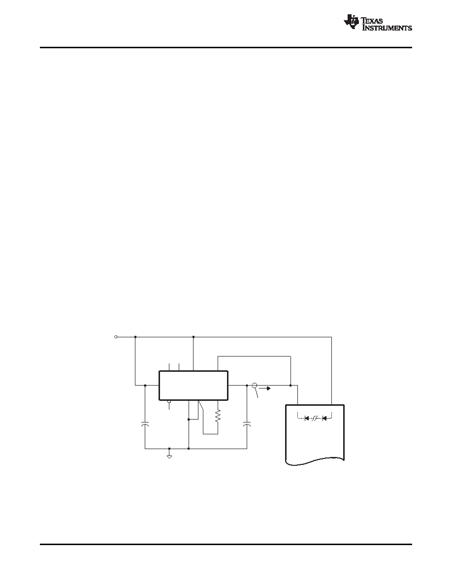
must be maintained(2). Figure 13 shows an application demonstrating the pre-bias startup capability. The startup
waveforms are shown in Figure 14. Note that the output current from the PTH03010W (IO) shows negligible
current until its output voltage rises above that backfed through the ASIC's intrinsic diodes.
Note: The pre-bias start-up feature is not compatible with Auto-Track. When the module is under Auto-Track
control, it will sink current if the output voltage is below that of a back-feeding source. To ensure a pre-bias
hold-off one of two approaches must be followed when input power is applied to the module. The Auto-Track
function must either be disabled(3), or the module's output held off (for at least 50 ms) using the Inhibit pin.
Either approach ensures that the Track pin voltage is above the set-point voltage at start up.
Notes:
1. Startup includes the short delay (approximately 10 ms) prior to the output voltage rising, followed by the rise
of the output voltage under the module's internal soft-start control. Startup is complete when the output
voltage has risen to either the set-point voltage or the voltage at the Track pin, whichever is lowest.
2. To ensure that the regulator does not sink current when power is first applied (even with a ground signal
applied to the Inhibit control pin), the input voltage must always be greater than the output voltage throughout
the power-up and power-down sequence.
3. The Auto-Track function can be disabled at power up by immediately applying a voltage to the module's
Track pin that is greater than its set-point voltage. This can be easily accomplished by connecting the Track
pin to VI.
Figure 13. Application Circuit Demonstrating Pre-Bias Startup
16
Copyright 2003–2009, Texas Instruments Incorporated
Product Folder Link(s) :PTH05050W
相關(guān)PDF資料 |
PDF描述 |
|---|---|
| PTH08080WAST | 2.25 A SWITCHING REGULATOR, 300 kHz SWITCHING FREQ-MAX, PDMA5 |
| PTH08080WAZ | 2.25 A SWITCHING REGULATOR, 300 kHz SWITCHING FREQ-MAX, PDMA5 |
| PTH08080WAS | 2.25 A SWITCHING REGULATOR, 300 kHz SWITCHING FREQ-MAX, PDMA5 |
| PTH08080WAZT | 2.25 A SWITCHING REGULATOR, 300 kHz SWITCHING FREQ-MAX, PDMA5 |
| PTH08T210WAZT | 1-OUTPUT DC-DC REG PWR SUPPLY MODULE |
相關(guān)代理商/技術(shù)參數(shù) |
參數(shù)描述 |
|---|---|
| PTH05050WADT | 制造商:ARTESYN 制造商全稱:Artesyn Technologies 功能描述:DC-DC CONVERTERS POLA Non-isolated |
| PTH05050WAH | 功能描述:DC/DC轉(zhuǎn)換器 6A 5V-In Wide Adj Module w/Auto-Trk RoHS:否 制造商:Murata 產(chǎn)品: 輸出功率: 輸入電壓范圍:3.6 V to 5.5 V 輸入電壓(標(biāo)稱): 輸出端數(shù)量:1 輸出電壓(通道 1):3.3 V 輸出電流(通道 1):600 mA 輸出電壓(通道 2): 輸出電流(通道 2): 安裝風(fēng)格:SMD/SMT 封裝 / 箱體尺寸: |
| PTH05050WAH | 制造商:POWER TRENDS 功能描述:IC DC/DC 5VIN 6A ADJ O/P 5050 |
| PTH05050WAHT | 制造商:ARTESYN 制造商全稱:Artesyn Technologies 功能描述:DC-DC CONVERTERS POLA Non-isolated |
| PTH05050WAS | 功能描述:DC/DC轉(zhuǎn)換器 21.6W 0.8V-3.6V 6A RoHS:否 制造商:Murata 產(chǎn)品: 輸出功率: 輸入電壓范圍:3.6 V to 5.5 V 輸入電壓(標(biāo)稱): 輸出端數(shù)量:1 輸出電壓(通道 1):3.3 V 輸出電流(通道 1):600 mA 輸出電壓(通道 2): 輸出電流(通道 2): 安裝風(fēng)格:SMD/SMT 封裝 / 箱體尺寸: |
發(fā)布緊急采購,3分鐘左右您將得到回復(fù)。