- 您現(xiàn)在的位置:買賣IC網(wǎng) > PDF目錄361292 > QL5064-33APB484I BUS CONTROLLER PDF資料下載
參數(shù)資料
| 型號: | QL5064-33APB484I |
| 英文描述: | BUS CONTROLLER |
| 中文描述: | 總線控制器 |
| 文件頁數(shù): | 12/37頁 |
| 文件大?。?/td> | 806K |
| 代理商: | QL5064-33APB484I |
第1頁第2頁第3頁第4頁第5頁第6頁第7頁第8頁第9頁第10頁第11頁當前第12頁第13頁第14頁第15頁第16頁第17頁第18頁第19頁第20頁第21頁第22頁第23頁第24頁第25頁第26頁第27頁第28頁第29頁第30頁第31頁第32頁第33頁第34頁第35頁第36頁第37頁
QL5064 QuickPCI Data Sheet
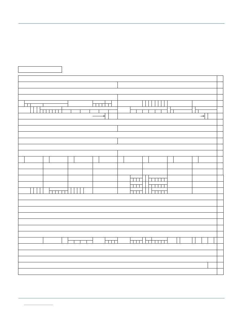
13.0 Control Registers
DMA Control and QL5064 registers can be accessed from the PCI bus or the back-end Control_DATA
bus. On the PCI side, these registers are accessed off of BAR 0, with offets 0x00 to 0xFF (below 0x100).
The breakdown of this memory space can be seen in the following table.
Receive FIFO0[63:0] (r only)
Receive FIFO1[63:0] (r only)
Transmit FIFO0[63:0] (w only)
Transmit FIFO1[63:0] (w only)
DMA 32/64#
DMA Arbitration Priority
Reserved
Reserved
Target Control Address[63:0] (r only)
Target Control Data[63:0] (r/w)
80
88
90
98
a0
a8
b0
b8
c0
c8
d0
d8
e0
e8
f0
f8
Single PCI Access Address Register[63:0] (r/w)
Single PCI Access Data Register[63:0] (r/w)
Reserved
User Incoming MB Full
Interrupt Mask[7:0]
User Incoming MB
Status [7:0]
0000_0000
0
BIST
Code[3:0]
DMA Cancel
Max
Retry
[1:0]
lat
en
FIFO
Thresh
TO[1:0]
User Outgoing MB
Empty [7:0]
User Outgoing MB Empty
Interrupt Mask[7:0]
User Outgoing MB
Status [7:0]
User Incoming MB
Full [7:0]
xmt1
rcv0
rcv1
chn
B
S
xmt0
DMA Interrupt
I
2
O Status
Error
xmt1
rcv0
rcv1
Chn
xmt0
R
P
M
M
I
2
O Interrupt
ifle
iplf
xmt1
rcv0
rcv1
xmt0
DMA Start/Done#
chn
B
D
xmt1
rcv0
rcv1
xmt0
FIFO
Flush
xmt1xmt0
000
0000
xmt1
rcv0
rcv1
Reserved
xmt0
xmt1[1:0]
rcv0[1:0]
rcv1[1:0]
xmt0[1:0]
0000
0000_00
Arb
Mode
[1:0]
B
S
CE
Chain
Ptr
Fetch
End
SPCI
0000_0000
0000_0000
0000
I
2
O Int Mask
0
S
I
0
0
0
0
B
M
DMA Interrupt Mask
xmt1
rcv0
rcv1
xmt0
chn
CE
S
M
user_be_req[7:0]
User region
[2:0]
0
T
T
T
T
W
63 62 61 60 59 58 57 56 55 54 53 52 51 50 49 48 47 46 45 44 43 42 41 40 39 38 37 36 35 34 33 32 31 30 29 28 27 26 25 24 23 22 21 20 19 18 17 16 15 14 13 12 11 10 9 8 7 6 5 4 3 2 1 0
BE En
[1:0]
0
Chn
0000_0000
0000_0000
0000_0000
PCI Incoming MB Empty
Interrupt Mask[7:0]
0000_0000
PCI Outgoing MB Empty
Interrupt Mask[7:0]
DMA SPC
rcv1 rcv0
000
oflf ople
ifle
iplf
oflf ople
ifle
iplf
oflf ople
xmt1xmt0
Master Write Address 0[63:0] (r/w)
Master Write Count Status0[31:0] (r only)
Master Write Transfer Count0[31:0] (r/w)
Master Write Address 1[63:0] (r/w)
Master Write Count Status1[31:0] (r only)
Single PCI Access
byte lanes[7:0]
cmd[3:0]
BAR Enable (r only)
4 3 2 1
5
rom
Master Write Transfer Count1[31:0] (r/w)
Receive FIFO 0
Byte Lane[7:0]
Target FIFO Control -- Emptyness Threshold
Target FIFO
Threshold
MSB's[3:0]
Reserved
00
08
10
18
20
28
30
38
40
48
50
58
60
68
70
78
User ID [7:0] (r only)
antifuse
Target Burst Request
BAR[5:0]
Receive FIFO 1
Byte Lane[7:0]
Target BAR Configuration (r only)
BAR3
BAR4
Chip Revision ID [7:0]
(r only)
Target Prefetch Cntl
BAR[5:0]
Master Read Address 0[63:0] (r/w) / Chain Descriptor Start Address [63:0] (r/w)
Master Read Count Status0[31:0] (r only)
Master Read Address 1[63:0] (r/w)
Master Read Count Status1[31:0] (r only)
00
(r/w)
00
00
(r/w)
(r/w)
(r/w)
Master Read Transfer Count0[31:0] (r/w)
Master Read Transfer Count1[31:0] (r/w)
00
User Incoming Mail 0
User Incoming Mail 1
User Incoming Mail 6 User Incoming Mail 5 User Incoming Mail 4
User Incoming Mail 2
User Incoming Mail 3
User Incoming Mail 7
User Outgoing Mail 0
User Outgoing Mail 1
User Outgoing Mail 6 User Outgoing Mail 5 User Outgoing Mail 4
User Outgoing Mail 2
User Outgoing Mail 3
User Outgoing Mail 7
I
2
O Interrupt Mask Bit [3]
I
2
O Interrupt Service Request Bit [3]
I
2
O Outbound Queue Pointer
I
2
O Inbound Queue Pointer
R
tag0
[1:0]
R
e
R
a
e
X
af
X
f
X
af
X
f
R
e
Bus Request
strt
0
R
0
R
a
e
BAR0
BAR1
BAR2
BAR3
BAR4
BAR5
BAR0
BAR1
BAR2
BAR5
0
00
0000
32
bit
w
w
e
/
Receive FIFO0
Almost Full[5:0]
(r/w)
Receive FIFO1
Almost Full[5:0]
(r/w)
XMIT FIFO 0
Almost Full[5:0]
XMIT FIFO 1
Almost Full[5:0]
00
Receive FIFO0
Almost Empty[5:0]
(r/w)
00
Receive FIFO1
Almost Empty[5:0]
(r/w)
XMIT FIFO 0
Almost Empty[5:0]
00
XMIT FIFO 1
Almost Empty[5:0]
00
63 62 61 60 59 58 57 56 55 54 53 52 51 50 49 48 47 46 45 44 43 42 41 40 39 38 37 36 35 34 33 32 31 30 29 28 27 26 25 24 23 22 21 20 19 18 17 16 15 14 13 12 11 10 9 8 7 6 5 4 3 2 1 0
Pipeline
Not Empty
XMT
0
XMT
1
XMT
0
XMT
1
RCV
0
RCV
1
USER Memory Map
相關PDF資料 |
PDF描述 |
|---|---|
| QL5064-33BPB456C | BUS CONTROLLER |
| QL5064-33BPB456I | BUS CONTROLLER |
| QL5064-33BPB484C | BUS CONTROLLER |
| QL5064-33BPB484I | BUS CONTROLLER |
| QL5064-66APB456C | BUS CONTROLLER |
相關代理商/技術參數(shù) |
參數(shù)描述 |
|---|---|
| QL5064-66APS484C-5541 | 制造商:QuickLogic Corporation 功能描述: |
| QL5064-66APS484I-5541 | 制造商:QuickLogic Corporation 功能描述: |
| QL5064-66BPS484C-5725 | 制造商:QuickLogic Corporation 功能描述: |
| QL5064-75CPS484C-5616 | 制造商:QuickLogic Corporation 功能描述: |
| QL5064-75CPS484I-5612 | 制造商:QuickLogic Corporation 功能描述: |
發(fā)布緊急采購,3分鐘左右您將得到回復。
