- 您現(xiàn)在的位置:買賣IC網(wǎng) > PDF目錄230912 > R5F64213KFB 32-BIT, FLASH, 64 MHz, MICROCONTROLLER, PQFP100 PDF資料下載
參數(shù)資料
| 型號: | R5F64213KFB |
| 元件分類: | 微控制器/微處理器 |
| 英文描述: | 32-BIT, FLASH, 64 MHz, MICROCONTROLLER, PQFP100 |
| 封裝: | 14 X 14 MM, 0.50 MM PITCH, PLASTIC, LQFP-100 |
| 文件頁數(shù): | 5/50頁 |
| 文件大小: | 777K |
| 代理商: | R5F64213KFB |
第1頁第2頁第3頁第4頁當前第5頁第6頁第7頁第8頁第9頁第10頁第11頁第12頁第13頁第14頁第15頁第16頁第17頁第18頁第19頁第20頁第21頁第22頁第23頁第24頁第25頁第26頁第27頁第28頁第29頁第30頁第31頁第32頁第33頁第34頁第35頁第36頁第37頁第38頁第39頁第40頁第41頁第42頁第43頁第44頁第45頁第46頁第47頁第48頁第49頁第50頁
REJ03B0237-0050 Rev.0.50 Jul 31, 2008
Page 11 of 111
Under development
Preliminary Specification
This is a preliminary specification and is subject to change.
R32C/121 Group
1. Overview
1.5
Pin Definitions and Functions
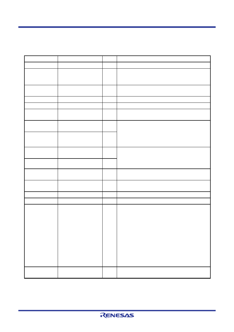
Table 1.7
Pin Definitions and Functions (1/3)
Function
Symbol
I/O
Description
Power supply
VCC, VSS
I
Applicable as follows: VCC = 3.0 to 5.5 V, VSS = 0 V
Connecting pins
for decoupling
capacitor
VDC0, VDC1
—
A decoupling capacitor for internal voltage should be
connected between VDC0 and VDC1
Analog power
supply
AVCC, AVSS
I
Power supply for the A/D converter. AVSS should be
connected to VSS
Reset input
RESET
I
The MCU is reset when this pin is driven low
CNVSS
I
This pin should be connected to VSS via a resistor.
Debug port
NSD
I/O
This pin is to communicate with a debugger. It should
be connected to VCC via a resistor of 1 to 4.7 k
Ω
Main clock input
XIN
I
Input/output for the main clock oscillator. A ceramic
resonator or a crystal oscillator should be connected
between pins XIN and XOUT. An external clock
should be input at the XIN while leaving the XOUT
open
Main clock output XOUT
O
Sub clock input
XCIN
I
Input/output for the sub clock oscillator. A crystal
oscillator should be connected between pins XCIN
and XCOUT. An external clock should be input at the
XCIN while leaving the XCOUT open
Sub clock output XCOUT
O
Clock output
CLKOUT
O
Output of the clock with the same frequency as fC,
f8, or f32
External interrupt
input
INT0 to INT5
I
Input for external interrupts
NMI input
P8_5/
NMI
I
Input for NMI
Key input interrupt
KI0 to KI3
I
Input for the key input interrupt
I/O ports
P0_0 to P0_7
P1_0 to P1_7
P2_0 to P2_7
P3_0 to P3_7
P4_0 to P4_7
P5_0 to P5_7
P6_0 to P6_7
P7_0 to P7_7
P8_0 to P8_4,
P8_6, P8_7
P9_3 to P9_7
P10_0 to P10_7
I/O
I/O ports in CMOS. Each port can be programmed to
input or output under the control of the direction
register.
Pull-up resistors are selected for following 4-pin
units, but are enabled only for the input pins: Pi_0 to
Pi_3 and Pi_4 to Pi_7 (i = 0 to 10)
Input port
P9_1
I
Input port in CMOS. Pull-up resistors are selected for
P9_1 and P9_3
相關(guān)PDF資料 |
PDF描述 |
|---|---|
| R8A77800ADBG | 32-BIT, FLASH, 402 MHz, RISC MICROCONTROLLER, PBGA449 |
| R8A77800ANBGV | 32-BIT, FLASH, 402 MHz, RISC MICROCONTROLLER, PBGA449 |
| R5F211A3XXXDD | 16-BIT, FLASH, 20 MHz, MICROCONTROLLER, PDIP20 |
| R5F211B4XXXNP | 16-BIT, FLASH, 20 MHz, MICROCONTROLLER, PQCC28 |
| R5F21367CNFP | 8-BIT, FLASH, 20 MHz, MICROCONTROLLER, PQFP64 |
相關(guān)代理商/技術(shù)參數(shù) |
參數(shù)描述 |
|---|---|
| R5F64213LFB | 制造商:RENESAS 制造商全稱:Renesas Technology Corp 功能描述:RENESAS MCU |
| R5F64216JFB | 制造商:RENESAS 制造商全稱:Renesas Technology Corp 功能描述:RENESAS MCU |
| R5F64216KFB | 制造商:RENESAS 制造商全稱:Renesas Technology Corp 功能描述:RENESAS MCU |
| R5F64216LFB | 制造商:RENESAS 制造商全稱:Renesas Technology Corp 功能描述:RENESAS MCU |
| R5F64217JFB | 制造商:RENESAS 制造商全稱:Renesas Technology Corp 功能描述:RENESAS MCU |
發(fā)布緊急采購,3分鐘左右您將得到回復(fù)。