- 您現(xiàn)在的位置:買賣IC網(wǎng) > PDF目錄376305 > RC86L50-1 (Electronic Theatre Controls, Inc.) VOICE SYNTHESIZER PDF資料下載
參數(shù)資料
| 型號: | RC86L50-1 |
| 廠商: | Electronic Theatre Controls, Inc. |
| 英文描述: | VOICE SYNTHESIZER |
| 中文描述: | 語音合成器 |
| 文件頁數(shù): | 10/48頁 |
| 文件大小: | 747K |
| 代理商: | RC86L50-1 |
第1頁第2頁第3頁第4頁第5頁第6頁第7頁第8頁第9頁當(dāng)前第10頁第11頁第12頁第13頁第14頁第15頁第16頁第17頁第18頁第19頁第20頁第21頁第22頁第23頁第24頁第25頁第26頁第27頁第28頁第29頁第30頁第31頁第32頁第33頁第34頁第35頁第36頁第37頁第38頁第39頁第40頁第41頁第42頁第43頁第44頁第45頁第46頁第47頁第48頁

10
RC8650 VOICE SYNTHESIZER
RC SYSTEMS
Note
The measurement cycle ends when there have been no High-
to-Low nor Low-to-High transitions on the BRD pin for 75 ms or longer.
Consequently, the RC8650 will ignore any data sent to it for a period of
75 ms after the “l(fā)ock-on” character has been received. The CTS# pin
is driven High during this time, and the acknowledgment character is
not transmitted until the RC8650 is actually ready to accept data. See
Figure 1.4.
Status messages
Real-time status information is provided via the TXD pin. Status are
transmitted as one-byte messages, shown in Table 1.3. Each mes-
sage correlates to a status flag in the Status Register, shown in Table
1.4. The specific character used, and whether it will be transmitted,
are functions of the VC and STM bits of the Protocol Options Register.
(The Protocol Options Register is described in Section 2.) For informa-
tion about how to obtain reading-progress status, see the Index Marker
command description.
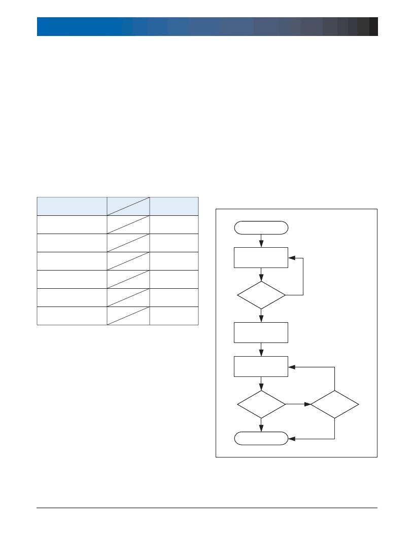
Table 1.3. Status Messages
Because the RC8650 can take up to 15 μs to accept data written to
it (AC Characteristics, t
YHWH
parameter), software drivers should wait
for RDY to drop to 0 after a byte is written in order to avoid overwriting
it with the next data byte. Not doing so could result in the loss of data.
Waiting for RDY to drop to 0 ensures that RDY will not falsely show that
the RC8650 is ready the next time the driver is called.
If a system interrupt can occur while waiting for RDY to become 0, or if
RDY cannot otherwise be checked at least once every 8 μs, a software
timeout should be enforced to avoid hanging up in the wait loop. The
time RDY stays 0 is relatively short (8 μs min.) and can be missed if in-
terrupted. The timeout should be at least 15 μs, which is the maximum
time for RDY to drop to 0 after writing a byte of data. In non time-criti-
cal applications, the output routine could simply delay 15 μs or longer
before exiting, without checking for RDY = 0 at all.
Figure 1.5 illustrates the recommended method of writing data to the
RC8650’s bus interface. This method should be used for writing all
types of data, including text, commands, tone generator and real time
audio data.
Bus/Printer Interface
The RC8650’s bus interface allows the RC8650 to be connected to a
microprocessor or microcontroller in the same manner as a static RAM
or I/O device, as shown in Figure 1.6. The microprocessor controls
all transactions with the RC8650 over the system data bus using the
RD and WR# signals. RD controls the reading of the RC8650’s Status
Register; WR# controls the transfer of data into the RC8650. The Status
Register bits and their definitions are shown in Table 1.4.
A registered bus transceiver is required for communication between
the RC8650 and microprocessor; two 74HCT374s placed back to
back may be substituted for the 74HCT652 shown in the figure. Prior
to each write operation to the RC8650, the host processor should verify
that the RC8650 is ready by testing the RDY status flag.
The RC8650 can also be interfaced to a PC’s printer port as shown
in Figure 1.6. A 74HCT374 can be used in place of the 74HCT652,
since bidirectional communication is not necessary. Handshaking is
performed automatically via the BUSY pin.
Figure 1.5. Recommended Method of Writing Data Via the Bus Interface
相關(guān)PDF資料 |
PDF描述 |
|---|---|
| RC86L50-2 | VOICE SYNTHESIZER |
| RC86L50-3 | VOICE SYNTHESIZER |
| RCM3200 | C-Programmable Module with Ethernet |
| RCV336ACFWSP | RCV336ACF/SP and RCV144ACF/SP Modem Device |
| RCV144ASP | RCV336ACF/SP and RCV144ACF/SP Modem Device |
相關(guān)代理商/技術(shù)參數(shù) |
參數(shù)描述 |
|---|---|
| RC86L50-2 | 制造商:未知廠家 制造商全稱:未知廠家 功能描述:VOICE SYNTHESIZER |
| RC86L50-3 | 制造商:未知廠家 制造商全稱:未知廠家 功能描述:VOICE SYNTHESIZER |
| RC86L60-1 | 制造商:未知廠家 制造商全稱:未知廠家 功能描述:CMOS, 3.3 Volt / 5 Volt Voice Synthesizer Chipset |
| RC86L60-2 | 制造商:未知廠家 制造商全稱:未知廠家 功能描述:CMOS, 3.3 Volt / 5 Volt Voice Synthesizer Chipset |
| RC86L60-3 | 制造商:未知廠家 制造商全稱:未知廠家 功能描述:CMOS, 3.3 Volt / 5 Volt Voice Synthesizer Chipset |
發(fā)布緊急采購,3分鐘左右您將得到回復(fù)。