- 您現(xiàn)在的位置:買賣IC網(wǎng) > PDF目錄373261 > RF1211 Analog IC PDF資料下載
參數(shù)資料
| 型號: | RF1211 |
| 英文描述: | Analog IC |
| 中文描述: | 模擬IC |
| 文件頁數(shù): | 1/2頁 |
| 文件大?。?/td> | 242K |
| 代理商: | RF1211 |
RF Monolithics, Inc.
RFM Europe
1999 by RF Monolithics, Inc. The stylized RFM logo are registered trademarks of RF Monolithics, Inc.
Phone: (972) 233-2903
Phone: 44 1963 251383
Fax: (972) 387-9148
Fax: 44 1963 251510
E-mail: info@rfm.com
http://www.rfm.com
RF1211-101499
Page 1 of 2
Electrical Characteristics
Characteristic
Sym
Notes
Minimum
Typical
Maximum
Units
Nominal Frequency
Insertion Loss
3 dB Passband
F
C
IL
BW
3
BW
3
2, 3, 4, 5, 6
3, 4, 7
2, 3, 4, 7
315.000
1.7
MHz
dB
kHz
3.0
±85
3 dB Reject
2, 3, 4, 7
±500
kHz
Rejection
at f
c
- 21.4 MHz (Image)
at f
c
- 10.7 MHz (LO)
Ultimate
Operating Case Temp.
4
40
50
dB
15
40
80
Temperature
T
C
T
O
f
O
FTC
|fA|
L
C
3, 7, 8
-35
+85
°C
Turnover Temperature
22
37
f
C
52
°C
Turnover Frequency
MHz
ppm/°C
2
ppm/yr
Freq. Temp. Coefficient
Absolute Value during the First Year
Series Inductance
Shunt Capacitance
0.032
10
Frequency Aging
3
External Impedance
1, 7
86 nH (Pin 1), 82 nH (Pin 2)
9
RFM RF1211
pF
Lid Symbolization (in addition to Lot and/or Date Codes)
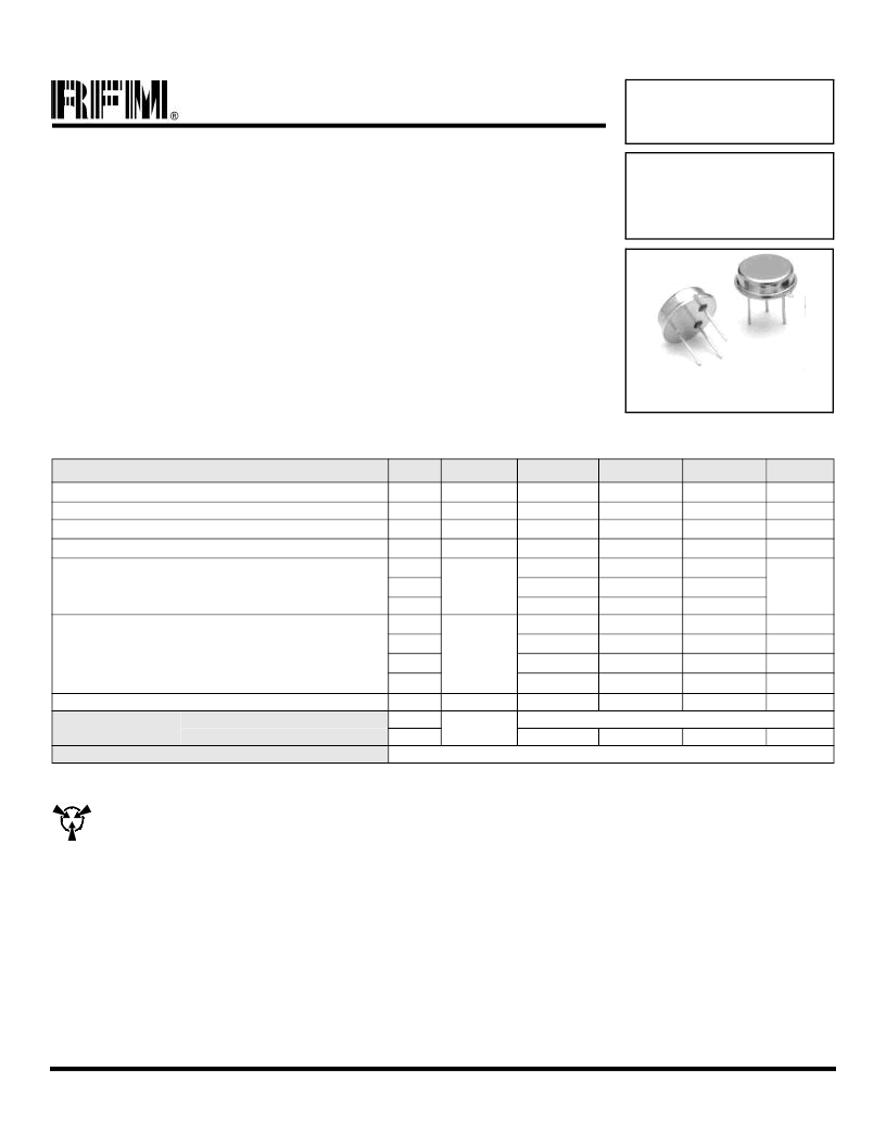
TO39-3 Case
Ideal Front-End Filter for USA Automotive Wireless Receivers
Low-Loss, Coupled-Resonator Quartz Design
Simple External Impedance Matching
Rugged TO39 Hermetic Package
The RF1211 is a low-loss, compact, and economical surface-acoustic-wave (SAW) filter designed to provide
front-end selectivity in 315.0 MHz receivers. Receiver designs using this filter include superhet with
10.7 MHz or 500 kHz IF, direct conversion and superregen. Typical applications of these receivers are wire-
less remote-control and security devices (especially for automotive keyless entry) operating in the USA
under FCC Part 15, in Canada under DOC RSS-210, and in Italy.
This coupled-resonator filter (CRF) uses selective null placement to provide suppression, typically greater
than 40 dB, of the LO and image spurious responses of superhet receivers with 10.7 MHz IF. RFM’s advanced
SAW design and fabrication technology is utilized to achieve high performance and very low loss with simple
external impedance matching (not included). Quartz construction provides excellent frequency stability over
a wide temperature range.
315.0 MHz
SAW Filter
RF1211
CAUTION: Electrostatic Sensitive Device. Observe precautions for handling.
Notes:
1. Typical test circuit is shown for TO-39 RF filters.
2. Passband and reject bands are specified in reference to f
C
.
3. All characteristics are specified over the operating temperature range and typical aging for 10 years.
4. Unless noted otherwise, all measurements are made with the filter installed in the specified test fixture. Note that insertion loss, bandwidth, and pass-
band shape are dependent on the impedance matching component values and quality. Demonstration circuits are available for confirmation of device
performance.
5. One or more of the following U.S. Patents apply: 4,454,488; 4,616,197; and other pending.
6. All equipment designs utilizing this product must be approved by the appropriate government agency prior to manufacture or sale.
7. The design, manufacturing process, and specifications of this device are subject to change without notice.
8. The turnover temperature, T
O
, is the temperature of maximum (or turnover) frequency, f
o
. The nominal frequency at any case temperature, T
C
, out-
side the operating temperature range may be calculated from: f = f
o
[1 - FTC (T
O
- T
C
)
2
].
相關(guān)PDF資料 |
PDF描述 |
|---|---|
| RF1254 | Analog IC |
| RF1283 | Analog IC |
| RF1306 | Analog IC |
| RF1316 | Analog IC |
| RF1327-1 | Analog IC |
相關(guān)代理商/技術(shù)參數(shù) |
參數(shù)描述 |
|---|---|
| RF1211-000 | 制造商:TE Connectivity 功能描述:SURGE PROTECTOR 170V SMA 50A |
| RF1211B | 制造商:RFM 制造商全稱:RF Monolithics, Inc 功能描述:315.0 MHz SAW Filter |
| RF1211C | 功能描述:信號調(diào)節(jié) 315.00MHz Narrowband Receiver Front End RoHS:否 制造商:EPCOS 產(chǎn)品:Duplexers 頻率:782 MHz, 751 MHz 頻率范圍: 電壓額定值: 帶寬: 阻抗:50 Ohms 端接類型:SMD/SMT 封裝 / 箱體:2.5 mm x 2 mm 工作溫度范圍:- 30 C to + 85 C 封裝:Reel |
| RF1211D | 制造商:未知廠家 制造商全稱:未知廠家 功能描述:315.0 MHz SAW Filter |
| RF1212-000 | 制造商:TE Connectivity 功能描述:SURGE PROTECTOR 220V SMA 50A |
發(fā)布緊急采購,3分鐘左右您將得到回復。