- 您現(xiàn)在的位置:買賣IC網(wǎng) > PDF目錄385768 > RF2449 (RF MICRO DEVICES INC) CDMA/FM LOW NOISE AMPLIFIER/MIXER 900MHZ DOWNCONVERTER PDF資料下載
參數(shù)資料
| 型號(hào): | RF2449 |
| 廠商: | RF MICRO DEVICES INC |
| 元件分類: | 無(wú)繩電話/電話 |
| 英文描述: | CDMA/FM LOW NOISE AMPLIFIER/MIXER 900MHZ DOWNCONVERTER |
| 中文描述: | TELECOM, CELLULAR, RF AND BASEBAND CIRCUIT |
| 封裝: | SSOP-24 |
| 文件頁(yè)數(shù): | 6/14頁(yè) |
| 文件大小: | 288K |
| 代理商: | RF2449 |
第1頁(yè)第2頁(yè)第3頁(yè)第4頁(yè)第5頁(yè)當(dāng)前第6頁(yè)第7頁(yè)第8頁(yè)第9頁(yè)第10頁(yè)第11頁(yè)第12頁(yè)第13頁(yè)第14頁(yè)
Preliminary
8-80
RF2449
Rev A4 001016
8
F
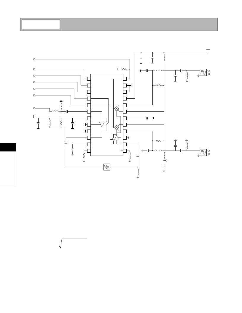
Application S chematic
1
2
3
4
5
6
7
8
9
10
11
12
24
23
22
21
20
19
18
17
16
15
14
13
33 nF
30 nH
6.8 nH
100 pF
6.8 nH
3.0 pF
22 k
33 k
1.5 nH 33 nF
22 nH
ENABLE
IP SET
IF SEL
LNA GAIN
MIX GAIN
*
100 pF
*NOTE:
Microstrip Inductor, Z
O
= 50
, L = 100 mils
Suggested component values for 85.38 MHz IF and
R
= 1 k
:
L1 = 470 nH
C1 = 10 pF
R = 7.5 k
RF IN
510
1 nF
V
CC
RF SAW Filter
56
LO IN
1 nF
R
L1
C1
L2
V
CC
C1
C2
L
Filter
IF2+
IF2-
100 pF
R
L1
C1
L2
1 nF
VCC
C1
C2
L
Filter
IF+
IF-
Output Interfac e Network
L1, C1 and R form a current combiner which performs
a differential to single-ended conversion at the IF fre-
quency and sets the output impedance. In most cases,
the resonance frequency is independent of R and can
be set according to the following equation:
Where C
EQ
is the equivalent stray capacitance and
capacitance looking into pins 16 and 17. An average
value to use for C
EQ
is 2.5pF.
R may then be used to set the output impedance
according to the following equation:
where R
OUT
is the desired output impedance and R
P
is
the parasitic equivalent parallel resistance of L1.
C1 should be chosen as high as possible, while main-
taining an R
P
of L1 that allows for the desired R
OUT
.
L2 and C2 serve dual purposes. L2 serves as an out-
put bias choke, and C2 serves as a series DC block.
In addition, L2 and C2 may be chosen to form an
impedance matching network if the input impedance of
the IF filter is not equal to ROUT. Otherwise, L2 is cho-
sen to be large and C2 is chosen to be large if a DC
path to ground is present in the IF filter, or omitted if the
filter is DC blocked.
f
IF
2
π
1
2
------
C
1
(
C
EQ
+
)
---------------------1
=
R
4
R
OUT
--------1
R
P
--1
1
–
–
=
相關(guān)PDF資料 |
PDF描述 |
|---|---|
| RF2451 | 3V LOW NOISE AMPLIFIER |
| RF2456 | CDMA/FM DOWNCONVERTER |
| RF2459 | 3V PCS DOWNCONVERTER |
| RF2460 | PCS CDMA LOW NOISE AMPLIFIER/MIXER 1500MHZ TO 2200MHZ DOWNCONVERTER |
| RF2461 | CDMA/FM LOW NOISE AMPLIFIER/MIXER 900MHZ DOWNCONVERTER |
相關(guān)代理商/技術(shù)參數(shù) |
參數(shù)描述 |
|---|---|
| RF2450 | 制造商:未知廠家 制造商全稱:未知廠家 功能描述:Analog IC |
| RF2451 | 制造商:RFMD 制造商全稱:RF Micro Devices 功能描述:3V LOW NOISE AMPLIFIER |
| RF2454 | 制造商:International Rectifier 功能描述: |
| RF2456 | 制造商:RFMD 制造商全稱:RF Micro Devices 功能描述:CDMA/FM DOWNCONVERTER |
| RF2459 | 制造商:RFMD 制造商全稱:RF Micro Devices 功能描述:3V PCS DOWNCONVERTER |
發(fā)布緊急采購(gòu),3分鐘左右您將得到回復(fù)。