- 您現(xiàn)在的位置:買賣IC網(wǎng) > PDF目錄385769 > RF2514 (RF MICRO DEVICES INC) VHF/UHF TRANSMITTER PDF資料下載
參數(shù)資料
| 型號: | RF2514 |
| 廠商: | RF MICRO DEVICES INC |
| 元件分類: | 通信及網(wǎng)絡 |
| 英文描述: | VHF/UHF TRANSMITTER |
| 中文描述: | SPECIALTY TELECOM CIRCUIT, QCC16 |
| 封裝: | 4 X 4 MM, QFN-16 |
| 文件頁數(shù): | 7/14頁 |
| 文件大?。?/td> | 268K |
| 代理商: | RF2514 |
Preliminary
11-33
RF2514
Rev A2 010215
11
T
transmission of the desired data. There is no need for
an external microprocessor to monitor the lock status,
although that can be done with a low current A/D con-
verter in a system micro, if needed. The lock detect cir-
cuitry
contains
an
internal
combined with a designer-chosen capacitor for a par-
ticular RC time constant, filters the lock detect signal.
This signal is then passed through an internal Schmitt
trigger and used to enable or disable the transmit
amplifier.
1k
resistor
which,
If the oscillator unlocks, even momentarily, the protec-
tion circuit quickly disables the output until lock is
achieved. These unlocks can be caused by low battery
voltage, poor power supply regulation, severe shock of
the crystal or VCO, antenna loading, component fail-
ure, or a myriad of unexpected single-point failures.
The RF2514 contains onboard band gap reference
voltage circuitry which provides a stable DC bias over
varying temperature and supply voltages. Additionally,
the device features a power-down mode, eliminating
battery disconnect switches.
Designing with the RF2514
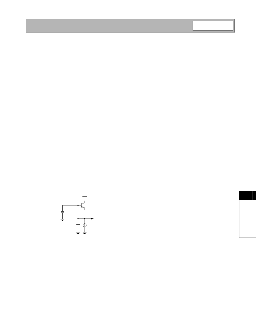
The reference oscillator is built around the onboard
transistor at pins 15 and 16. The intended topology is
that of a Colpitts oscillator. The Colpitts oscillator is
quite common and requires few external components,
making it ideal for low cost solutions. The topology of
this type of oscillator is as seen in the following figure.
This type of oscillator is a parallel resonant circuit for a
fundamental mode crystal. The transistor amplifier is
an emitter follower and the voltage gain is developed
by the tapped capacitor impedance transformer. The
series combination of C
1
and C
2
act in parallel with the
input capacitance of the transistor to capacitively load
the crystal.
The nominal capacitor values can be calculated with
the following equations
and
The load capacitance, C
load
, is a characteristic of the
crystal used; freq
MHz
is the oscillator frequency in
MHz. The frequency can be adjusted by either chang-
ing C2 or by placing a variable capacitor in series with
the crystal. As an example, assume a desired oscillator
frequency of 14MHz and a load capacitance of 32pF.
C
1
=137.1pF and C
2
=41.7pF.
These capacitor values provide a starting point. The
drive level of the oscillator should be checked by look-
ing at the signal at the OSC E pin. It has been found
that the level at this pin should generally be around
500mV
PP
or less. This will reduce the reference spur
levels and reduce noise produced by distortion. If this
level is higher than 500mV
PP
then decrease the value
of C
1
. The values of these capacitors are usually
adjusted during design to meet performance goals,
such as minimizing the start-up time.
An important part of the overall design is the voltage
controlled oscillator. The VCO is configured as a differ-
ential amplifier. The VCO range is set by the external
inductor(s) and is fine-tuned via internal varactor
diodes. The varactors are tuned by the loop filter output
voltage through a 4k
resistor. (Refer to the internal
schematic for RESNTR- in the pin description table.)
To tune the VCO the designer only needs to calculate
the value of the inductor(s) connected to RESNTR-
and RESNTR+. The inductor value is determined by
the equation:
In this equation, f is the desired operating frequency
and L is the value of the inductor required. In the case
of a two-inductor resonator configuration, the value of L
is halved due to the inductors being in each leg. The
value C is the amount of capacitance presented by the
varactors and parasitics. For calculation purposes,
1.5pF should be used. As an example, assume an
operating frequency of 868MHz. The calculated induc-
tor value is 22.4nH. A 22nH inductor (two 10nH induc-
tors for the two-inductor configuration) would be
appropriate as the closest available value. Be aware
X1
C2
C1
V
CC
C
1
60
C
freq
MHz
-----------------------
=
C
2
C
load
-------------
C
1
------
–
--------------------------
=
L
2
π
f
----------------
2
1
C
---
=
相關(guān)PDF資料 |
PDF描述 |
|---|---|
| RF2516 | VHF/UHF TRANSMITTER |
| RF2601 | GAIN CONTROLLED IF AMPLIFIER |
| RF2603 | 2.8V PCS UPCONVERTER |
| RF2607 | CDMA/FM RECEIVE AGC AMPLIFIER |
| RF2608 | 887368322 |
相關(guān)代理商/技術(shù)參數(shù) |
參數(shù)描述 |
|---|---|
| RF2514_06 | 制造商:RFMD 制造商全稱:RF Micro Devices 功能描述:VHF/UHF TRANSMITTER |
| RF2514_1 | 制造商:RFMD 制造商全稱:RF Micro Devices 功能描述:VHF/UHF TRANSMITTER |
| RF2514PCBA | 制造商:RFMD 制造商全稱:RF Micro Devices 功能描述:VHF/UHF TRANSMITTER |
| RF2514PCBA-41X | 制造商:RFMD 制造商全稱:RF Micro Devices 功能描述:VHF/UHF TRANSMITTER |
| RF2516 | 制造商:RF Micro Devices Inc 功能描述:IC TXRX 500MHZ QSOP-16 |
發(fā)布緊急采購,3分鐘左右您將得到回復。