- 您現(xiàn)在的位置:買賣IC網(wǎng) > PDF目錄376313 > RM3183 (Electronic Theatre Controls, Inc.) Dual ARINC 429 Line Receiver PDF資料下載
參數(shù)資料
| 型號(hào): | RM3183 |
| 廠商: | Electronic Theatre Controls, Inc. |
| 英文描述: | Dual ARINC 429 Line Receiver |
| 中文描述: | 雙的ARINC 429線路接收器 |
| 文件頁(yè)數(shù): | 2/12頁(yè) |
| 文件大?。?/td> | 86K |
| 代理商: | RM3183 |

RM3183
PRODUCT SPECIFICATION
2
Functional Description
The RM3183 contains two discrete ARINC 429 receiver
channels. Each channel contains three main sections: a
resistor-diode input network, a window comparator, and a
logic output buffer stage. The first stage provides overvolt-
age protection and biases the signal using voltage dividers
and current sources which are internally connected to the
+V
L
logic supply. This configuration provides excellent
input common mode rejection and a stable reference voltage
for the window comparators. Because the threshold for
switching is determined by this circuitry,
recommended for the +V
L
supply. The test inputs will set the
outputs to a predetermined state for built-in test capability.
±
5% tolerance is
The ARINC inputs must be forced to 0V when using the test
inputs. If the test inputs are not used, they should be
grounded.
The window comparator stage generates two serial data
streams, one having logic 1 states corresponding to ARINC
“High” states (OUTA), and the other having logic 1 states
corresponding to ARINC “Low” states (OUTB). An ARINC
“Null” state at the inputs forces both outputs to logic 0.
Thus, the ARINC clock signal is recovered by applying a
NOR function to OUTA and OUTB.
The output stage generates a TTL compatible logic output
capable of driving several gate inputs.
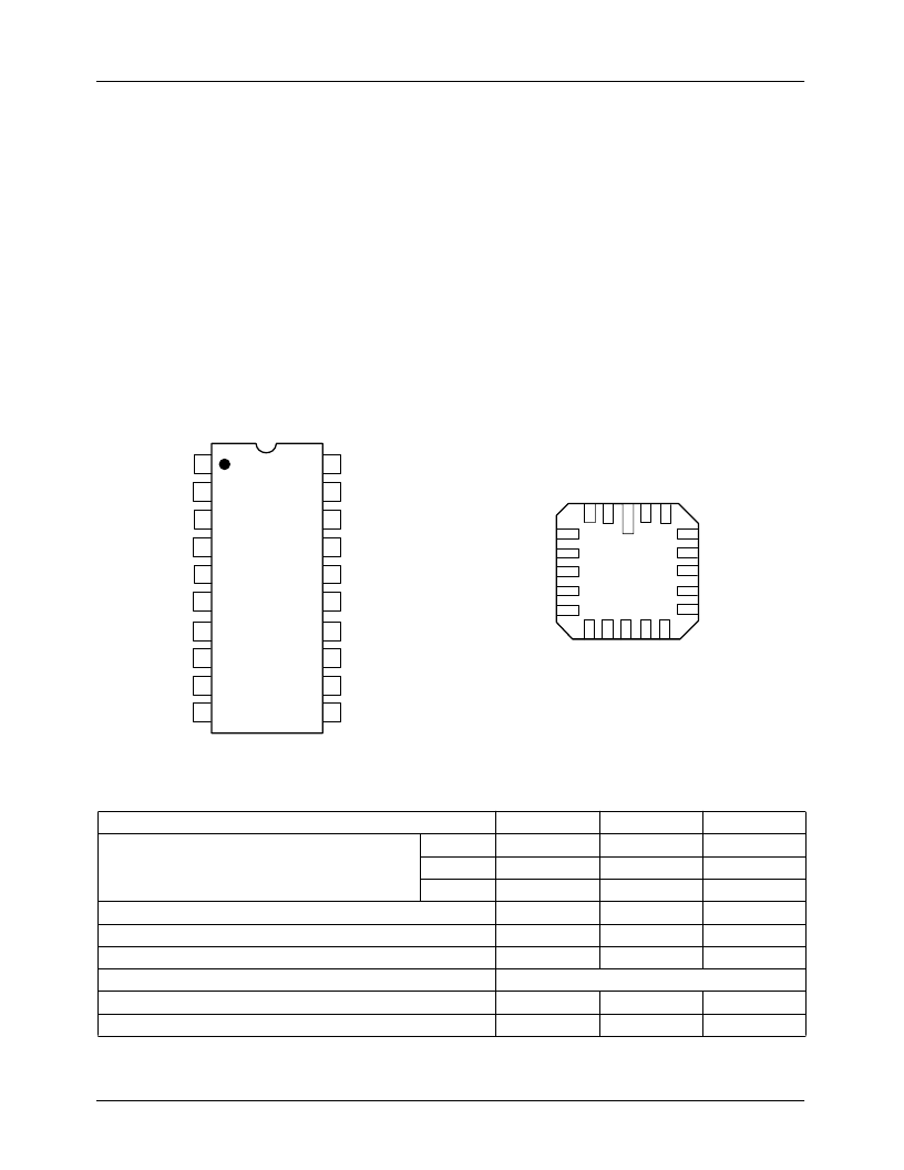
Pin Assignments
Absolute Maximum Ratings
Parameter
Supply Voltage
Min.
Max.
+20
–20
+7
+125
+150
±
50
Units
VDC
VDC
VDC
°
C
°
C
V
+V
–V
+V
S
S
L
Operating Temperature Range
Storage Temperature Range
Input Voltage Range
Output Short Circuit Duration
Internal Power Dissipation
Lead Soldering Temperature (60 seconds)
-55
-65
Not protected
900
+300
mW
°
C
20
2
3
4
5
6
7
8
9
10
-V
S
TestA
Ceramic Dip
Top View
Cap2B
In2B
Out2B
In2A
Cap2A
Out2A
+V
L
NC
11
12
13
14
15
16
17
18
19
TestB
+V
S
Out1B
NC
GND
Out1A
In1B
Cap1B
In1A
Cap1A
65-3183-02
65-3183-03
4
5
6
7
8
In2B
Out2B
In2A
Cap2A
Out2A
14
15
16
17
18
GND
Out1A
In1B
Cap1B
In1A
C
1
T
2
-
S
T
C
1
2
3
N
O
+
S
N
+
L
1
1
1
1
9
LCC
Top View
相關(guān)PDF資料 |
PDF描述 |
|---|---|
| RM3183L | Dual ARINC 429 Line Receiver |
| RM3183S | Dual ARINC 429 Line Receiver |
| RM400HA-34S | Super Fast Recovery Single Diode Module (400 Amperes/1700 Volts) |
| RM4136 | Quad General-Purpose Operational Amplifiers(通用型四運(yùn)放) |
| RM4136FK | QUAD GENERAL-PURPOSE OPERATIONAL AMPLIFIERS |
相關(guān)代理商/技術(shù)參數(shù) |
參數(shù)描述 |
|---|---|
| RM3183CH | 制造商:未知廠家 制造商全稱:未知廠家 功能描述:Line Receiver |
| RM3183D | 制造商:未知廠家 制造商全稱:未知廠家 功能描述:Line Receiver |
| RM3183D/883B | 制造商:未知廠家 制造商全稱:未知廠家 功能描述:Line Receiver |
| RM3183L | 制造商:未知廠家 制造商全稱:未知廠家 功能描述:Dual ARINC 429 Line Receiver |
| RM3183L/883B | 制造商:未知廠家 制造商全稱:未知廠家 功能描述:Line Receiver |
發(fā)布緊急采購(gòu),3分鐘左右您將得到回復(fù)。