- 您現(xiàn)在的位置:買賣IC網(wǎng) > PDF目錄373301 > RO2149 Analog IC PDF資料下載
參數(shù)資料
| 型號: | RO2149 |
| 英文描述: | Analog IC |
| 中文描述: | 模擬IC |
| 文件頁數(shù): | 2/2頁 |
| 文件大?。?/td> | 259K |
| 代理商: | RO2149 |
311.063 MHz SAW Resonator
RF Monolithics, Inc.
RFM Europe
1999 by RF Monolithics, Inc. The stylized RFM logo are registered trademarks of RF Monolithics, Inc.
Phone: (972) 233-2903
Phone: 44 1963 251383
Fax: (972) 387-9148
Fax: 44 1963 251510
E-mail: info@rfm.com
http://www.rfm.com
RO2149-102799
Page 2 of 2
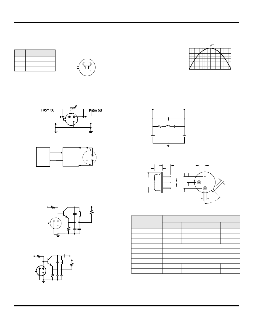
Electrical Connections
This one-port, two-terminal SAW resonator is bidirectional. The terminals
are interchangeable with the exception of circuit board layout.
Typical Test Circuit
The test circuit inductor, L
TEST
, is tuned to resonate with the static capaci-
tance, C
O
at F
C
.
Typical Application Circuits
Temperature Characteristics
Equivalent LC Model
The following equivalent LC model is valid near resonance:
Case Design
Pin
Connection
1
2
3
Terminal 1
Terminal 2
Case Ground
Network
Analyzer
Network
Analyzer
Electrical Test:
1
2
3
50
Source at
F
C
Low-Loss
Matching
N50
Power Test:
P
P
INCIDENT
INCIDENT
CW RF Power Dissipation =
-
REFLECTED
REFLECTED
P
P
3
2
1
MPS-H10
+9VDC
47
RF Bypass
L1
C1
C2
200k
ModInput
ROXXXX
470
Typical Low-Power Transmitter Application:
1
2
3
(Antenna)
+VDC
RF Bypass
L1
C2
Bottom View
Typical Local Oscillator Application:
1
2
3
Output
+VDC
C1
Dimensions
Millimeters
Inches
Min
Max
Min
Max
A
B
C
D
E
F
G
H
J
9.30
3.18
3.50
0.366
0.125
0.138
2.50
0.46 Nominal
5.08 Nominal
2.54 Nominal
2.54 Nominal
0.098
0.018 Nominal
0.200 Nominal
0.100 Nominal
0.100 Nominal
1.02
0.040
1.40
0.055
The curve shown on the right
accounts for resonator contri-
bution only and does not in-
clude oscillator temperature
characteristics.
-80 -60 -40 -20
0 +20 +40 +60
0
-50
-100
-150
+80
-200
0
-50
-100
-150
-200
f
C
= f
O
, T
C
= T
O
T = T
C
- T
O
( °C )
(
o
)
0.5 pF*
0.25 pF*
Cp
Co=
+
*Case Parasitics
R
L
C
0.5 pF*
Cp
1
2
3
M
M
M
B
45°
J
(2 places)
D
(3 places)
H
G
E
F
C
A
Bottom View
Pin 1
Pin 2
Pin 3
相關(guān)PDF資料 |
PDF描述 |
|---|---|
| RO2150 | Analog IC |
| RO2150A | Analog IC |
| RO2171 | Analog IC |
| RO2179B | Analog IC |
| RO2180B | Analog IC |
相關(guān)代理商/技術(shù)參數(shù) |
參數(shù)描述 |
|---|---|
| RO2150 | 制造商:未知廠家 制造商全稱:未知廠家 功能描述:Analog IC |
| RO2150A | 制造商:未知廠家 制造商全稱:未知廠家 功能描述:Analog IC |
| RO2156A | 制造商:RFM 制造商全稱:RF Monolithics, Inc 功能描述:868.95 MHz SAW Resonator |
| RO2156A-1 | 制造商:RFM 制造商全稱:RF Monolithics, Inc 功能描述:868.95 MHz SAW Resonator |
| RO2156A-2 | 制造商:RFM 制造商全稱:RF Monolithics, Inc 功能描述:868.95 MHz SAW Resonator |
發(fā)布緊急采購,3分鐘左右您將得到回復(fù)。