- 您現(xiàn)在的位置:買賣IC網(wǎng) > PDF目錄385813 > SAA6713AH (NXP Semiconductors N.V.) XGA analog input flat panel controller PDF資料下載
參數(shù)資料
| 型號: | SAA6713AH |
| 廠商: | NXP Semiconductors N.V. |
| 英文描述: | XGA analog input flat panel controller |
| 中文描述: | 模擬輸入的XGA液晶控制器 |
| 文件頁數(shù): | 12/100頁 |
| 文件大小: | 498K |
| 代理商: | SAA6713AH |
第1頁第2頁第3頁第4頁第5頁第6頁第7頁第8頁第9頁第10頁第11頁當(dāng)前第12頁第13頁第14頁第15頁第16頁第17頁第18頁第19頁第20頁第21頁第22頁第23頁第24頁第25頁第26頁第27頁第28頁第29頁第30頁第31頁第32頁第33頁第34頁第35頁第36頁第37頁第38頁第39頁第40頁第41頁第42頁第43頁第44頁第45頁第46頁第47頁第48頁第49頁第50頁第51頁第52頁第53頁第54頁第55頁第56頁第57頁第58頁第59頁第60頁第61頁第62頁第63頁第64頁第65頁第66頁第67頁第68頁第69頁第70頁第71頁第72頁第73頁第74頁第75頁第76頁第77頁第78頁第79頁第80頁第81頁第82頁第83頁第84頁第85頁第86頁第87頁第88頁第89頁第90頁第91頁第92頁第93頁第94頁第95頁第96頁第97頁第98頁第99頁第100頁
2004 Apr 05
12
Philips Semiconductors
Product specification
XGA analog input flat panel controller
SAA6713AH
7
FUNCTIONAL DESCRIPTION
In this chapter detailed information for the general
configuration of the SAA6713AH is provided as well as
detailed background information belonging to certain
submodules of the device. Due to the high complexity of
the device functionality this section should be studied very
carefully.
7.1
Programming registers
7.1.1
C
ONFIGURATION PARAMETER MAPPING
The SAA6713AH operation is controlled by configuration
parameters, that can be multiple-bit words or consist of
only a single bit. The configuration parameters are
mapped to bits of the 8 bit I
2
C-bus programming registers,
that are accessible via the I
2
C-bus interface. Read-out
data such as measurement results or interrupt states is
mapped to readable I
2
C-bus registers.
The I
2
C-bus registers are organized in pages. Generally, a
register can only be accessed if the particular page is
activated with the exception of global registers, so
non-global registers are addressed by the I
2
C-bus
subaddress in combination with the matching active page,
but global registers are addressed by the subaddress
independently of the active page.
The global registers are mapped to I
2
C-bus subaddresses
F8H to FFH. The active page is defined by page_select at
subaddress FFH. In general, registers belonging to the
same functional unit are mapped onto the same page. The
I
2
C-bus register pages are shown in Table 2.
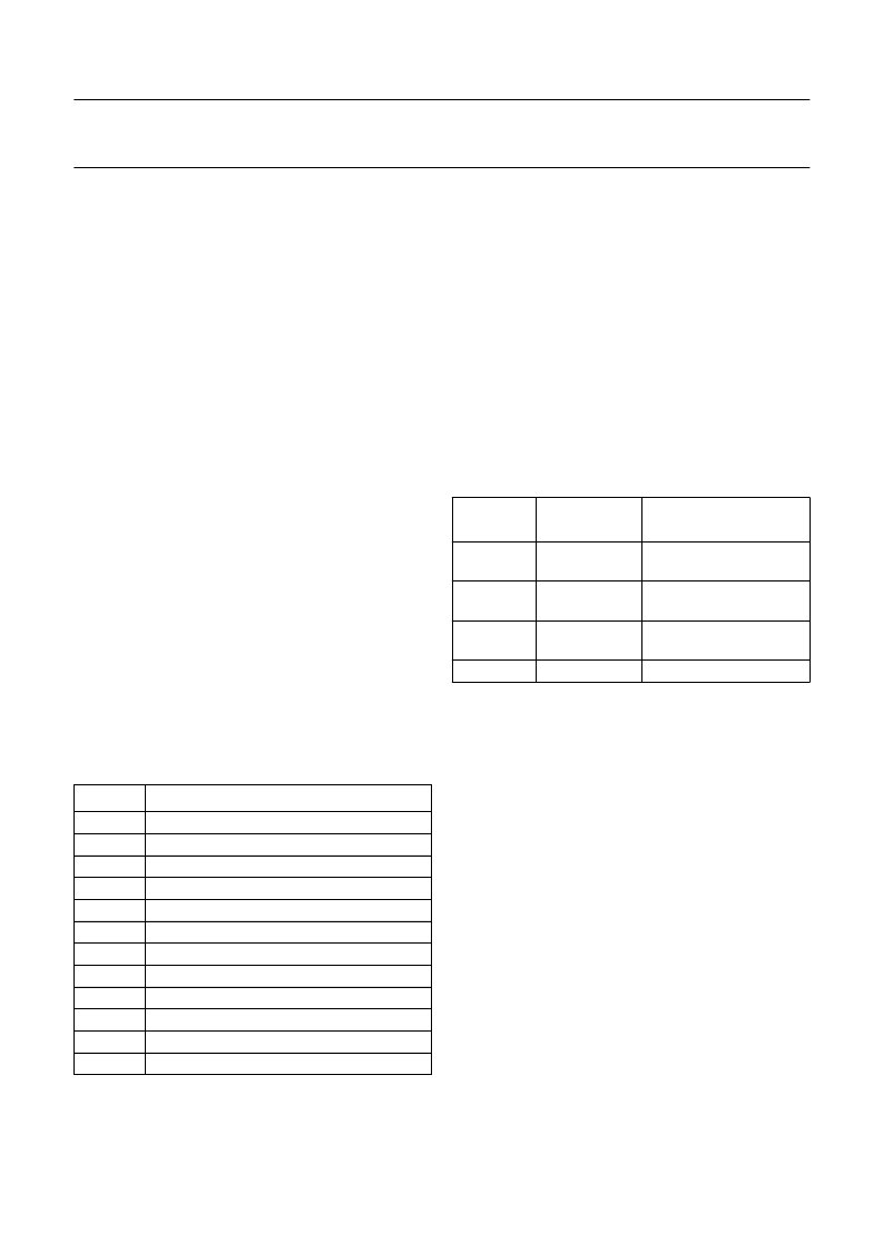
Table 2
I
2
C-bus register pages
7.1.2
I
2
C-
BUS INTERFACE
The I
2
C-bus serial interface consists of two pins: the serial
clock pin SCL and the serial data pin SDA.
7.1.2.1
Transmission bit rate
The I
2
C-bus interface supports transmission speeds of up
to 3.4 Mbits/s, given that a minimum system clock rate is
provided. The required system clock rate depends on the
target I
2
C-bus bit rate, which is the clock rate applied to
pin SCL, and the spike suppression mode selected by
iic_spike_mode in register IIC_MODE (03H at page 0) as
shown in Table 3. If iic_spike_mode is set to 2, a high
oversampling rate is used and the most effective spike
suppression is provided.
Table 3
I
2
C-bus spike suppression modes
7.1.2.2
I
2
C-bus transmission timing
The SAA6713AH only operates as a slave and the clock
pin SCL is exclusively input. Data is transmitted and
received at I/O pin SDA. The SDA is an open-drain stage
with an external pull-up resistor. When a logic 0 is applied,
the bus is pulled to LOW-level by the output buffer. When
a logic 1 is applied, the output buffer switches to 3-state
and the pull-up resistor pulls the bus up to HIGH-level.
Data transfers are initiated by an I
2
C-bus master device by
sending the start condition, which is a change from
HIGH-to-LOW level at SDA when SCL is at HIGH-level
(see Fig.3).
Data is transmitted byte wise. Data changes on SDA are
allowed only when SCL is at LOW-level and data is
sampled on the positive edge of SCL. The first transmitted
byte is the recipients I
2
C-bus device address and the data
transfer direction bit. All byte transfers are acknowledged
by the recipient by pulling SDA to LOW-level for the
following cycle.
PAGE
FUNCTIONAL UNIT
0
1
2
3
4
5
6
7
8
9
10
11
control unit and clock generator
ADC control
mode detection
auto-adjustment
input interface and picture generator
colour processing
decoupling FIFO
scalers
OSD
OSD colour definition
gamma correction and dithering
TFT output interface
iic_spike_
mode[1:0]
SYSTEM
CLOCK
>6
×
I
2
C-bus
bit rate
>6
×
I
2
C-bus
bit rate
>16
×
I
2
C-bus
bit rate
not used
DESCRIPTION
00
2-out-of-2 filter
01
2-out-of-3 majority filter
10
4-out-of-4 filter
11
相關(guān)PDF資料 |
PDF描述 |
|---|---|
| SAA6713H | XGA dual input flat panel controller |
| SAA7110 | Digital Multistandard Colour Decoder(數(shù)字多標(biāo)準(zhǔn)彩色譯碼器) |
| SAA7111 | Video Input Processor VIP |
| SAA7120H | Digital video encoder |
| SAA7152 | Digital Video Comb Filter DCF |
相關(guān)代理商/技術(shù)參數(shù) |
參數(shù)描述 |
|---|---|
| SAA6713AH/V1 | 制造商:PHILIPS 制造商全稱:NXP Semiconductors 功能描述:XGA analog input flat panel controller |
| SAA6713H | 制造商:PHILIPS 制造商全稱:NXP Semiconductors 功能描述:XGA dual input flat panel controller |
| SAA6713H/V1 | 制造商:PHILIPS 制造商全稱:NXP Semiconductors 功能描述:XGA dual input flat panel controller |
| SAA6721 | 制造商:PHILIPS 制造商全稱:NXP Semiconductors 功能描述:SXGA RGB to TFT graphics engine |
| SAA6721E | 制造商:PHILIPS 制造商全稱:NXP Semiconductors 功能描述:SXGA RGB to TFT graphics engine |
發(fā)布緊急采購,3分鐘左右您將得到回復(fù)。