- 您現(xiàn)在的位置:買賣IC網(wǎng) > PDF目錄385813 > SAA7187 (NXP Semiconductors N.V.) Digital video encoder (DENC2-SQ)(數(shù)字視頻編碼器) PDF資料下載
參數(shù)資料
| 型號(hào): | SAA7187 |
| 廠商: | NXP Semiconductors N.V. |
| 英文描述: | Digital video encoder (DENC2-SQ)(數(shù)字視頻編碼器) |
| 中文描述: | 數(shù)字視頻編碼器(DENC2 -倚)(數(shù)字視頻編碼器) |
| 文件頁(yè)數(shù): | 4/18頁(yè) |
| 文件大小: | 197K |
| 代理商: | SAA7187 |
第1頁(yè)第2頁(yè)第3頁(yè)當(dāng)前第4頁(yè)第5頁(yè)第6頁(yè)第7頁(yè)第8頁(yè)第9頁(yè)第10頁(yè)第11頁(yè)第12頁(yè)第13頁(yè)第14頁(yè)第15頁(yè)第16頁(yè)第17頁(yè)第18頁(yè)
Philips Semiconductors
Clock and synchronization signals of SAA7187 and SAA7188
Application note for digital video encoder
May 1994
4
3.0
RASTER CONTROL OUTPUT
SIGNALS
The NTSC / PAL video encoder has an
internal synchronization circuitry. For the
purpose of this application note it is referred
to as horizontal counter – counting in clocks
along a horizontal line – and as vertical
counter – counting in half lines through a
video field. A third counter for color field
sequence identification is implemented to
support the interlace characteristic of the
video signal as well as to distinguish the
NTSC four color field sequence, and PAL
eight color field sequence. The IC has four
Raster Control pins (RCxx), which reflect the
timing and status of the internal
synchronization circuitry. Two of them carry
vertical / field synchronization signals, and
two carry horizontal / line synchronization
information. One of each pair is output only,
the other one can be defined as output or as
input, to re-trigger the internal
synchronization circuitry. (The nomenclature
of these four pins is related to data flow in a
particular application, but should not be
understood as restriction.) All four signals are
defined on one and the same internal
synchronization circuitry.
3.1
Vertical – Field – Reference
Output Signals
The digital encoder SAA7187 and SAA7188A
have two pins to output field reference Raster
Control signals. RCM1 on pin 29 has output
only functionality, and a fixed (nominal) signal
polarity. RCV1 on pin 6 has selectable signal
polarity and can be used as output or as input
to re-trigger internal timing (see later in this
application note).
3.1.1
For both field reference outputs, one signal
out of a set of the following three signal types
can be selected independently.
Field Reference Signal Types
VS
Vertical Sync signal is nominal active
(nominal high) for 3 lines if 60Hz
timing is selected, or for 2.5 lines if
50Hz timing is selected, i.e., during
those half lines, in which the analog
CVBS output contains the main
vertical sync pulses..
FS
Frame Sync signal is an odd_/even
signal, that is active (nominal low)
during every first i.e. odd field, and
inactive (nominal high) during every
second, i.e., even field in the 2:1
interlace scheme of two fields in one
frame. The first field is that field, in
which the first main vertical sync
pulse (serration pulse) starts in
coincidence with the begin of a line.
FSEQ
The color Field SEQuence signal
indicates the start of the color field
sequence (see CCIR report 624,
e.g.). FSEQ is active (nominal high)
during the first field of the 4-(NTSC)
or 8-(PAL) color field sequence for
standard encoding. FSEQ is inactive
(nominal low) through all the other
fields.
The position of the output signals VS, FS and
FSEQ as RCM1 at pin 29, as well as RCV1
at pin 6, has a fix timing relationship to the
internal horizontal and vertical counters and
is not directly effected by programming of
HTRIG or VTRIG. The leading (nominal
rising) edge of VS, and all edges of FS and
FSEQ occur at nominal field start (according
to CCIR nomenclature), and on half line
boundaries. For standard interlaced mode
and nominal field length, FS is low for 262.5
(312.5) lines and high for 262.5 (312.5) lines,
for example. The leading (nominal falling)
edge of FS or the leading (nominal rising)
edge of FSEQ indicates the begin of a frame,
the begin of a field, and also the begin of a
line, and can be used to reset/trigger external
vertical as well as horizontal synchronization
counter.
If the encoder is forced into non-interlaced
mode through external re-trigger, the FS
function is meaningless. If non-standard
encoding regarding subcarrier-to-line
coupling is applied, selection of FSEQ
function is meaningless.
Selecting any of these signal for output as
RCM1 on pin 29 or as RCV1 on pin 6 has no
direct effect on internal blanking or other
processing in the encoder IC itself. RCM1
and RCV1 as output are just auxiliary timing
signals for use by the application
environment, to support the video signal
source (e.g., MPEG decompression circuitry,
or video memory controller, or graphics
generator) to time its data stream output.
3.1.2
Pin 29 RCM1 has output only function and
carries field synchronizing raster control
information. Via two SRCM bits in
subaddress 6Dhex one of three types of field
sync signals can be selected.
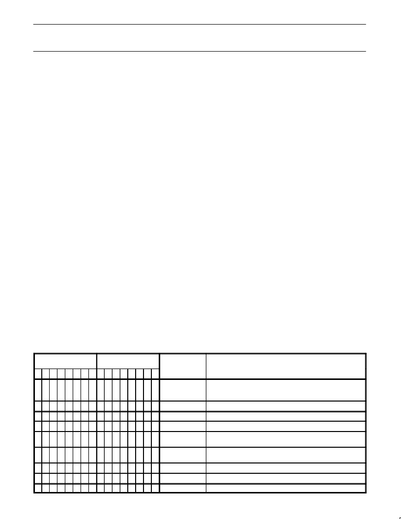
Pin 29 : RCM1
Table 2. Selection of RCM1 signal function on Pin 29
F = relevant function, x = other function/signal definition, – = don’t care
BITS UNDER
SUBADDRESS 6Dh
BITS UNDER
SUBADDRESS 61h
SHORT NAME
FUNCTION
RESULTING SIGNAL
7 6
5
4
3
2
1
0
7 6
5
4
3
2
1
0
–
x
x
x
x
x
x
F
FISE
select field frequency (V–pulse sequence)
select number of clocks/line (selects FSEQ as 4 or 8 field se-
quence)
– –
–
–
F F
x
x
SRCM
select RCM1 signal function
0
0
0
VS 50Hz
active
high
for
2.5
lines at begin of every field
0
0
1
VS 60Hz
active
high
for
3
lines at begin of every field
0
1
0
FS 50Hz
low
in
first
(odd) field,
312.5
lines
high in second (even) field, 312.5 lines
0
1
1
FS 60Hz
low
in
first
(odd) field,
262.5
lines
high in second (even) field, 262.5 lines
1
0
0
FSEQ 50Hz
high
in the
first
field
of 8
field sequence
1
0
1
FSEQ 60Hz
high
in the
first
field
of 4
field sequence
1
1
x
n.a.
reserved, do not use
相關(guān)PDF資料 |
PDF描述 |
|---|---|
| SAA7188A | Digital Video Encoder (DENC2-M)(數(shù)字視頻編碼器(DENC2-M)) |
| SAA7201 | Integrated MPEG2 AVG Decoder(綜合MPEG音頻視頻圖表譯碼器) |
| SAA7201H | Integrated MPEG2 AVG decoder |
| SAA7212 | Integrated MPEG2 AVG Decoder(綜合MPEG音頻視頻圖表譯碼器) |
| SAA7212H | Integrated MPEG AVG decoder |
相關(guān)代理商/技術(shù)參數(shù) |
參數(shù)描述 |
|---|---|
| SAA7187WP | 制造商:NXP Semiconductors 功能描述: |
| SAA7188 | 制造商:PHILIPS 制造商全稱:NXP Semiconductors 功能描述:Digital Video Encoder DENC2-M |
| SAA7188A | 制造商:PHILIPS 制造商全稱:NXP Semiconductors 功能描述:Digital Video Encoder DENC2-M |
| SAA7188AWP | 制造商:NXP Semiconductors 功能描述:COLOR SIGNAL ENCODER, PQCC68 |
| SAA7191B | 制造商:PHILIPS 制造商全稱:NXP Semiconductors 功能描述:Digital Multistandard Colour Decoder, Square Pixel DMSD-SQP |
發(fā)布緊急采購(gòu),3分鐘左右您將得到回復(fù)。