- 您現(xiàn)在的位置:買賣IC網(wǎng) > PDF目錄376338 > SCAN15MB200TSQ (NATIONAL SEMICONDUCTOR CORP) Dual 1.5 Gbps 2:1/1:2 LVDS Mux/Buffer with Pre-Emphasis and IEEE 1149.6 PDF資料下載
參數(shù)資料
| 型號: | SCAN15MB200TSQ |
| 廠商: | NATIONAL SEMICONDUCTOR CORP |
| 元件分類: | 通用總線功能 |
| 英文描述: | Dual 1.5 Gbps 2:1/1:2 LVDS Mux/Buffer with Pre-Emphasis and IEEE 1149.6 |
| 中文描述: | DUAL LINE TRANSCEIVER, PQCC48 |
| 封裝: | LLP-48 |
| 文件頁數(shù): | 11/12頁 |
| 文件大?。?/td> | 599K |
| 代理商: | SCAN15MB200TSQ |

Interfacing LVDS to LVPECL
An LVDS driver consists of a current source (nominal 3.5mA)
which drives a CMOS differential pair. It needs a differential
resistive load in the range of 70 to 130
to generate LVDS
levels. In a system, the load should be selected to match
transmission line characteristic differential impedance so
that the line is properly terminated. The termination resistor
should be placed as close to the receiver inputs as possible.
When interfacing an LVDS driver with a non-LVDS receiver,
one only needs to bias the LVDS signal so that it is within the
common mode range of the receiver. This may be done by
using separate biasing voltage which demands another
power supply. Some receivers have required biasing voltage
available on-chip (V
T
, V
TT
or V
BB
).
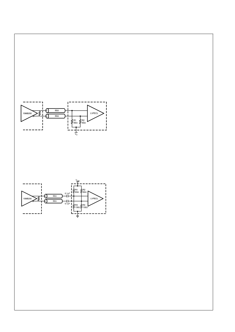
Figure 5
illustrates interface between an LVDS driver and a
LVPECL with a V
pin available. R1 and R2, if not present in
the receiver (Note 17), provide proper resistive load for the
driver and termination for the transmission line, and V
T
sets
desired bias for the receiver.
Figure 6
illustrates AC coupled interface between an LVDS
driver and LVPECL receiver without a V
pin available. The
resistors R1, R2, R3, and R4, if not present in the receiver
(Note 17), provide a load for the driver, terminate the trans-
mission line, and bias the signal for the receiver.
Note 17:
The bias networks shown above for LVPECL drivers and receivers
may or may not be present within the driver device. The LVPECL driver and
receiver specification must be reviewed closely to ensure compatibility be-
tween the driver and receiver terminations and common mode operating
ranges.
Design-For-Test (DfT) Features
IEEE 1149.1 SUPPORT
The SCAN15MB200 supports a fully compliant IEEE 1149.1
interface. The Test Access Port (TAP) provides access to
boundary scan cells at each LVTTL I/O on the device for
interconnect testing. Differential pins are included in the
same boundary scan chain but instead contain IEEE1149.6
cells. IEEE1149.6 is the improved IEEE standard for testing
high-speed differential signals.
Refer to the BSDL file located on National’s website for the
details of the SCAN15MB200 IEEE 1149.1 implementation.
IEEE 1149.6 SUPPORT
AC-coupled differential interconnections on very high speed
(1+ Gbps) data paths are not testable using traditional IEEE
1149.1 techniques. The IEEE 1149.1 structures and meth-
ods are intended to test static (DC-coupled), single ended
networks. IEEE 1149.6 is specifically designed for testing
high-speed differential, including AC coupled networks.
The SCAN15MB200 is intended for high-speed signalling up
to 1.5 Gbps and includes IEEE1149.6 on all differential in-
puts and outputs.
FAULT INSERTION
Fault Insertion is a technique used to assist in the verification
and debug of diagnostic software. During system testing
faults are "injected" to simulate hardware failure and thus
help verify the monitoring software can detect and diagnose
these faults. In the SCAN15MB200 an IEEE1149.1 "stuck-
at" instruction can create a stuck-at condition, either high or
low, on any pin or combination of pins. A more detailed
description of the stuck-at feature can be found in NSC
Applications note AN-1313.
Packaging Information
The Leadless Leadframe Package (LLP) is a leadframe
based chip scale package (CSP) that may enhance chip
speed, reduce thermal impedance, and reduce the printed
circuit board area required for mounting. The small size and
very low profile make this package ideal for high density
PCBs used in small-scale electronic applications such as
cellular phones, pagers, and handheld PDAs. The LLP pack-
age is offered in the no Pullback configuration. In the no
Pullback configuration the standard solder pads extend and
terminate at the edge of the package. This feature offers a
visible solder fillet after board mounting.
The LLP has the following advantages:
Low thermal resistance
Reduced electrical parasitics
Improved board space efficiency
Reduced package height
Reduced package mass
For more details about LLP packaging technology, refer to
applications note AN-1187, "Leadless Leadframe Package"
20132863
FIGURE 5. DC Coupled LVDS to LVPECL Interface
20132864
FIGURE 6. AC Coupled LVDS to LVPECL Interface
S
www.national.com
11
相關PDF資料 |
PDF描述 |
|---|---|
| SCAN15MB200TSQX | Dual 1.5 Gbps 2:1/1:2 LVDS Mux/Buffer with Pre-Emphasis and IEEE 1149.6 |
| SCAN162512SM | Low Voltage Universal 16-bit IEEE 1149.1 Bus Transceiver with TRI-STATE Outputs |
| SCAN16512 | Low Voltage Universal 16-bit IEEE 1149.1 Bus Transceiver with TRI-STATE Outputs |
| SCAN16512SM | Low Voltage Universal 16-bit IEEE 1149.1 Bus Transceiver with TRI-STATE Outputs |
| SCANH162512SM | Low Voltage Universal 16-bit IEEE 1149.1 Bus Transceiver with TRI-STATE Outputs |
相關代理商/技術參數(shù) |
參數(shù)描述 |
|---|---|
| SCAN15MB200TSQ/NOPB | 功能描述:LVDS 接口集成電路 RoHS:否 制造商:Texas Instruments 激勵器數(shù)量:4 接收機數(shù)量:4 數(shù)據(jù)速率:155.5 Mbps 工作電源電壓:5 V 最大功率耗散:1025 mW 最大工作溫度:+ 85 C 封裝 / 箱體:SOIC-16 Narrow 封裝:Reel |
| SCAN15MB200TSQX | 功能描述:LVDS 接口集成電路 RoHS:否 制造商:Texas Instruments 激勵器數(shù)量:4 接收機數(shù)量:4 數(shù)據(jù)速率:155.5 Mbps 工作電源電壓:5 V 最大功率耗散:1025 mW 最大工作溫度:+ 85 C 封裝 / 箱體:SOIC-16 Narrow 封裝:Reel |
| SCAN15MB200TSQX/NOPB | 功能描述:LVDS 接口集成電路 RoHS:否 制造商:Texas Instruments 激勵器數(shù)量:4 接收機數(shù)量:4 數(shù)據(jù)速率:155.5 Mbps 工作電源電壓:5 V 最大功率耗散:1025 mW 最大工作溫度:+ 85 C 封裝 / 箱體:SOIC-16 Narrow 封裝:Reel |
| SCAN15MB200TSQXNOPB | 制造商:National Semiconductor 功能描述:LVDS Repeater 0.5V 48-Pin LLP EP T/R |
| SCAN162512ASM | 制造商:Texas Instruments 功能描述:BUS TRANSCEIVER 16BIT IEEE 162512 |
發(fā)布緊急采購,3分鐘左右您將得到回復。