- 您現(xiàn)在的位置:買賣IC網(wǎng) > PDF目錄299917 > SN75ALS180NE4 (TEXAS INSTRUMENTS INC) LINE TRANSCEIVER, PDIP14 PDF資料下載
參數(shù)資料
| 型號(hào): | SN75ALS180NE4 |
| 廠商: | TEXAS INSTRUMENTS INC |
| 元件分類: | Buffer和線驅(qū)動(dòng) |
| 英文描述: | LINE TRANSCEIVER, PDIP14 |
| 封裝: | ROHS COMPLIANT, PLASTIC, DIP-14 |
| 文件頁(yè)數(shù): | 1/21頁(yè) |
| 文件大?。?/td> | 555K |
| 代理商: | SN75ALS180NE4 |
當(dāng)前第1頁(yè)第2頁(yè)第3頁(yè)第4頁(yè)第5頁(yè)第6頁(yè)第7頁(yè)第8頁(yè)第9頁(yè)第10頁(yè)第11頁(yè)第12頁(yè)第13頁(yè)第14頁(yè)第15頁(yè)第16頁(yè)第17頁(yè)第18頁(yè)第19頁(yè)第20頁(yè)第21頁(yè)
SN65ALS180, SN75ALS180
DIFFERENTIAL DRIVER AND RECEIVER PAIRS
SLLS052G – AUGUST 1987 – REVISED APRIL 2003
1
POST OFFICE BOX 655303
DALLAS, TEXAS 75265
D Meet or Exceed the Requirements of
TIA/EIA-422-B, TIA/EIA-485-A and
ITU Recommendation V.11
D High-Speed Advanced Low-Power Schottky
Circuitry
D Designed for 25-Mbaud Operation in Both
Serial and Parallel Applications
D Low Skew Between Devices ...6 ns Max
D Low Supply-Current Requirements
. . . 30 mA Max
D Individual Driver and Receiver I/O Pins With
Dual VCC and Dual GND
D Wide Positive and Negative Input/Output
Bus Voltage Ranges
D Driver Output Capacity . . . ±60 mA
D Thermal Shutdown Protection
D Driver Positive- and Negative-Current
Limiting
D Receiver Input Impedance . . . 12 k Min
D Receiver Input Sensitivity . . . ±200 mV Max
D Receiver Input Hysteresis . . . 60 mV Typ
D Operate From a Single 5-V Supply
D Glitch-Free Power-Up and Power-Down
Protection
description/ordering information
The SN65ALS180 and SN75ALS180 differential driver and receiver pairs are integrated circuits designed for
bidirectional data communication on multipoint bus-transmission lines. They are designed for balanced
transmission lines and meet TIA/EIA-422-B, TIA/EIA-485-A, and ITU Recommendation V.11.
ORDERING INFORMATION
TA
PACKAGE
ORDERABLE
PART NUMBER
TOP-SIDE
MARKING
PDIP (N)
Tube of 25
SN75ALS180N
0
°C to 70°C
SOIC (D)
Tube of 50
SN75ALS180D
75ALS180
SOIC (D)
Reel of 2500
SN75ALS180DR
75ALS180
–40
°Cto85°C
SOIC (D)
Tube of 50
SN65ALS180D
65ALS180
–40
°C to 85°C
SOIC (D)
Reel of 2500
SN65ALS180DR
65ALS180
Package drawings, standard packing quantities, thermal data, symbolization, and PCB design guidelines are
available at www.ti.com/sc/package.
Copyright
2003, Texas Instruments Incorporated
PRODUCTION DATA information is current as of publication date.
Products conform to specifications per the terms of Texas Instruments
standard warranty. Production processing does not necessarily include
testing of all parameters.
Please be aware that an important notice concerning availability, standard warranty, and use in critical applications of
Texas Instruments semiconductor products and disclaimers thereto appears at the end of this data sheet.
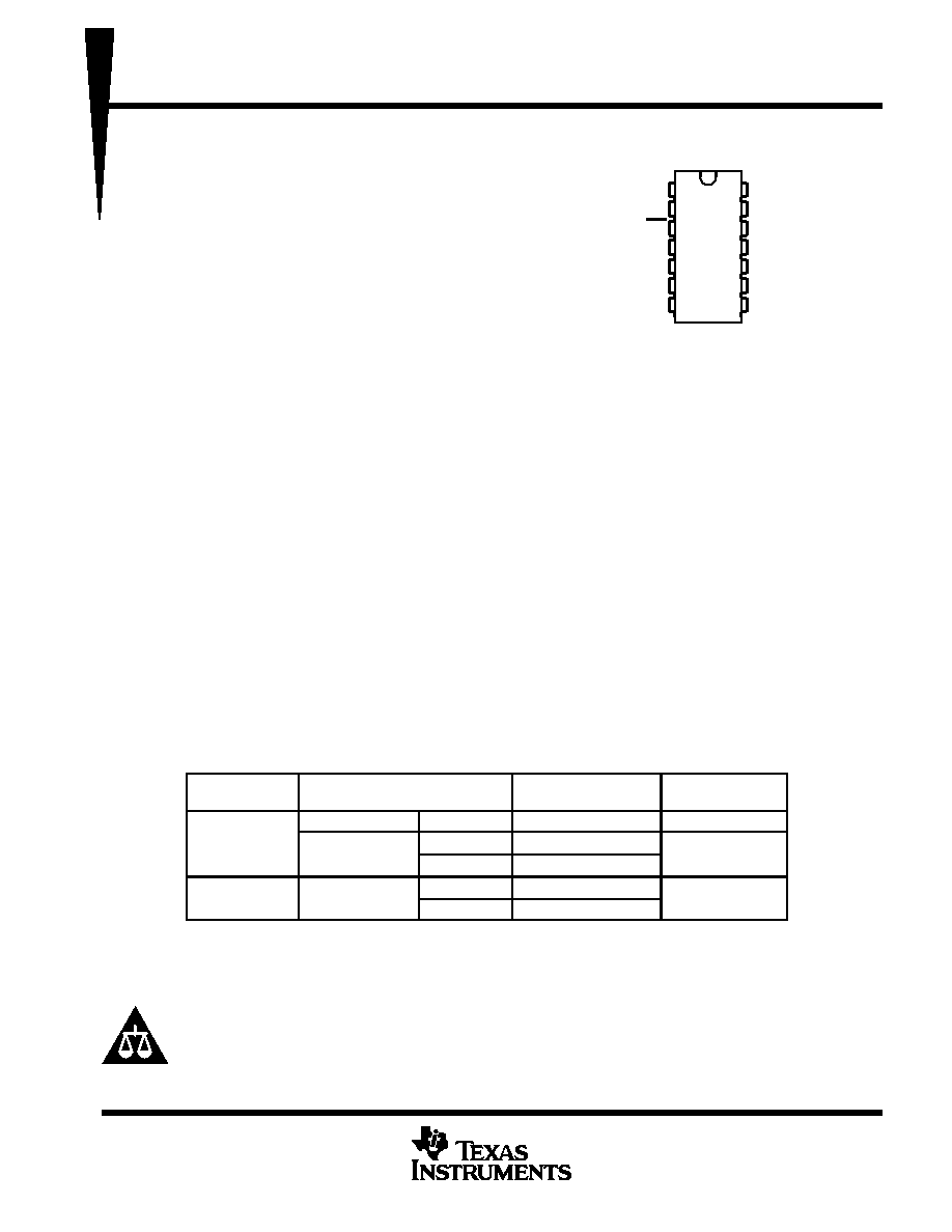
1
2
3
4
5
6
7
14
13
12
11
10
9
8
NC
R
RE
DE
D
GND
VCC
A
B
Z
Y
NC
SN65ALS180 ...D PACKAGE
SN75ALS180 ...D OR N PACKAGE
(TOP VIEW)
NC – No internal connection
These devices meet or exceed the requirements of TIA/EIA-485-A, except for the Generator Contention Test (para. 3.4.2) and the Generator
Current Limit (para. 3.4.3). The applied test voltage ranges are –6 V to 8 V for the SN75ALS180 and –4 V to 8 V for the SN65ALS180.
相關(guān)PDF資料 |
PDF描述 |
|---|---|
| SN75C1154NE4 | QUAD LINE TRANSCEIVER, PDIP20 |
| SN75C1154NSRE4 | QUAD LINE TRANSCEIVER, PDSO20 |
| SN75C3223EDBG4 | DUAL LINE TRANSCEIVER, PDSO20 |
| SN75C3223EDBRG4 | DUAL LINE TRANSCEIVER, PDSO20 |
| SN75C3223EDBR | DUAL LINE TRANSCEIVER, PDSO20 |
相關(guān)代理商/技術(shù)參數(shù) |
參數(shù)描述 |
|---|---|
| SN75ALS181 | 制造商:TI 制造商全稱:Texas Instruments 功能描述:DIFFERENTIAL DRIVER AND RECEIVER PAIR |
| SN75ALS181_08 | 制造商:TI 制造商全稱:Texas Instruments 功能描述:DIFFERENTIAL DRIVER AND RECEIVER PAIR |
| SN75ALS181_10 | 制造商:TI 制造商全稱:Texas Instruments 功能描述:DIFFERENTIAL DRIVER AND RECEIVER PAIR |
| SN75ALS181N | 功能描述:RS-422/RS-485 接口 IC Diff Pairs RoHS:否 制造商:Maxim Integrated 數(shù)據(jù)速率:1136 Kbps 工作電源電壓:3 V to 5.5 V 電源電流:5.9 mA 工作溫度范圍:- 40 C to + 85 C 安裝風(fēng)格:SMD/SMT 封裝 / 箱體:SOIC-28 封裝:Tube |
| SN75ALS181N | 制造商:Texas Instruments 功能描述:LEADED PROCESS COMPATIBLE ((NW)) 制造商:Texas Instruments 功能描述:IC, RS422/RS485 TRANSCEIVER, 5.25V DIP14 |
發(fā)布緊急采購(gòu),3分鐘左右您將得到回復(fù)。