- 您現(xiàn)在的位置:買賣IC網(wǎng) > PDF目錄372187 > SP6132HV High Voltage Synchronous Buck Controller PDF資料下載
參數(shù)資料
| 型號: | SP6132HV |
| 英文描述: | High Voltage Synchronous Buck Controller |
| 中文描述: | 高電壓同步降壓控制器 |
| 文件頁數(shù): | 11/14頁 |
| 文件大小: | 314K |
| 代理商: | SP6132HV |

11
Date: 8/4/04
SP6132 Wide Input, 300KHz Synchronous PWM Controller Copyright 2004 Sipex Corporation
APPLICATIONS INFORMATION: Continued
The goal of loop compensation is to manipulate
loop frequency response such that its gain crosses
over 0db at a slope of -20db/dec. The first step
of compensation design is to pick the loop
crossover frequency. High crossover frequency
is desirable for fast transient response, but often
jeopardizes the system stability. Crossover fre-
quency should be higher than the ESR zero but
less than 1/5 of the switching frequency. The
ESR zero is contributed by the ESR associated
with the output capacitors and can be deter-
mined by:
Z(ESR)
=
1
2
π
C
OUT
R
ESR
The next step is to calculated the complex con-
jugate poles contributed by the LC output filter,
P(LC)
=
1
2
π
L C
OUT
Fr(Hz)
Error Amplify Gain
Condition:
20 Log (RZ2/R1)
(dB)
1
1
1
1
1
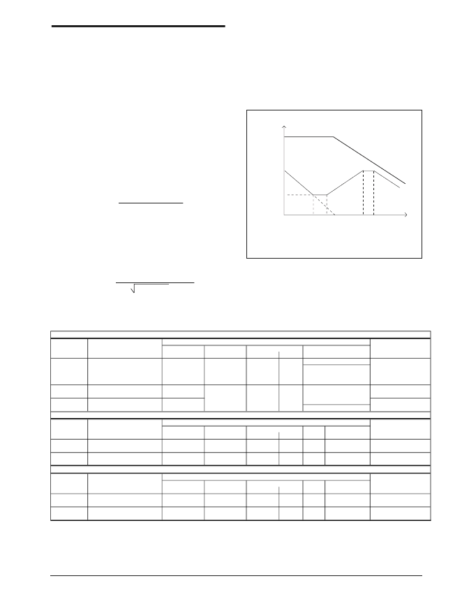
Bode Plot of Type III Error Amplify Compensation.
When the output capacitors are of a Ceramic
Type, the SP6132CU Evaluation Board requires
a Type III compensation circuit to give a phase
boost of 180
°
in order to counteract the effects of
an under damped resonance of the output filter
at the double pole frequency.
Table 1. Input and Output Stage Components Selection Charts.
Series R
mOhms
4.30
4.50
8.60
Isat
(A)
12.0
12.2
17.0
Manufacturer
Website
www.easymagnet.com
www.tdk.com
www.coilcraft.com
LxW(mm)
12.6x12.6
12.5x12.8
14.7x15.2
Ht.(mm)
4.5
6.0
8.0
2.7
2.7
3.3
Easy Magnet SC5018-2R7M
TDK RLF12560T-2R7N110
Coilcraft DO5010P-332HC
Shielded Ferrite Core
Shielded Ferrite Core
Unshielded Ferrite Core
1.2
1.2
1.5
1.9
Easy Magnet SC5018-1R2M
Inter-Technical SC4015-1R2M
Coilcraft DO5010P-152HC
TDK RLF12560T-1R9N120
1.96
4.37
4.00
3.60
20.0
17.0
25.0
13.2
12.6x12.6
10.0x10.0
14.7x15.2
12.5x12.8
4.5
3.8
8.0
6.0
Shielded Ferrite Core
Shielded Ferrite Core
Unshielded Ferrite Core
Shielded Ferrite Core
www.easymagnet.com
www.inter-technical.com
www.coilcraft.com
www.tdk.com
ESR
Ripple Current
(A) @ 45C
4.00
Voltage
(V)
16.0
Capacitor
Type
X5R Ceramic
Manufacturer
Website
www.tdk.com
ohms (max)
0.002
LxW(mm)
3.2x2.5
Ht.(mm)
2.0
22
TDK C3225X5R1C226M
47
TDK C3225X5R0J476M
0.002
4.00
3.2x2.5
2.5
6.3
X5R Ceramic
www.tdk.com
MOSFETS - SURFACE MOUNT
RDS(on)
ohms (max)
0.005
ID Current
(A)
21.0
Voltage
(V)
30.0
Foot Print
Manufacturer
Website
www.fairchildsemi.com
nC (Typ)
37.0
nC (Max)
48.0
N-Channel
Fairchild Semi FDS7088N3
SO-8
N-Channel
Vishay Si4336DY
0.004
25.0
32.0
50.0
30.0
SO-8
www.Vishay.com
Note: Components highlighted in
bold
are those used on the SP6132 Evaluation Board.
INDUCTORS - SURFACE MOUNT
CAPACITORS - SURFACE MOUNT
Capacitor Specification
Capacitance(u
F)
Inductance
(uH)
Size
Inductor Type
Size
Manufacturer/Part No.
Manufacturer/Part No.
Inductor Specification
MOSFET
Manufacturer/Part No.
MOSFET Specification
Qg
相關(guān)PDF資料 |
PDF描述 |
|---|---|
| SP6133 | Evaluation Board Manual |
| SP6133_06 | Evaluation Board Manual |
| SP6133EB | Evaluation Board Manual |
| SP6133ER1 | Evaluation Board Manual |
| SP61346 | Dual Supply Synchronous Buck Controller |
相關(guān)代理商/技術(shù)參數(shù) |
參數(shù)描述 |
|---|---|
| SP6133 | 制造商:SIPEX 制造商全稱:Sipex Corporation 功能描述:Evaluation Board Manual |
| SP6133_06 | 制造商:SIPEX 制造商全稱:Sipex Corporation 功能描述:Evaluation Board Manual |
| SP6133EB | 功能描述:DC/DC 開關(guān)控制器 Synchronous Buck Controller RoHS:否 制造商:Texas Instruments 輸入電壓:6 V to 100 V 開關(guān)頻率: 輸出電壓:1.215 V to 80 V 輸出電流:3.5 A 輸出端數(shù)量:1 最大工作溫度:+ 125 C 安裝風格: 封裝 / 箱體:CPAK |
| SP6133ER1 | 制造商:SIPEX 制造商全稱:Sipex Corporation 功能描述:Evaluation Board Manual |
| SP6133ER1/TR | 制造商:SIPEX 制造商全稱:Sipex Corporation 功能描述:Synchronous Buck Controller |
發(fā)布緊急采購,3分鐘左右您將得到回復。