- 您現(xiàn)在的位置:買賣IC網(wǎng) > PDF目錄98143 > ST10F168-Q2 (STMICROELECTRONICS) 16-BIT, FLASH, 25 MHz, MICROCONTROLLER, PQFP144 PDF資料下載
參數(shù)資料
| 型號: | ST10F168-Q2 |
| 廠商: | STMICROELECTRONICS |
| 元件分類: | 微控制器/微處理器 |
| 英文描述: | 16-BIT, FLASH, 25 MHz, MICROCONTROLLER, PQFP144 |
| 封裝: | 28 X 28 MM, PLASTIC, QFP-144 |
| 文件頁數(shù): | 19/76頁 |
| 文件大?。?/td> | 483K |
| 代理商: | ST10F168-Q2 |
第1頁第2頁第3頁第4頁第5頁第6頁第7頁第8頁第9頁第10頁第11頁第12頁第13頁第14頁第15頁第16頁第17頁第18頁當(dāng)前第19頁第20頁第21頁第22頁第23頁第24頁第25頁第26頁第27頁第28頁第29頁第30頁第31頁第32頁第33頁第34頁第35頁第36頁第37頁第38頁第39頁第40頁第41頁第42頁第43頁第44頁第45頁第46頁第47頁第48頁第49頁第50頁第51頁第52頁第53頁第54頁第55頁第56頁第57頁第58頁第59頁第60頁第61頁第62頁第63頁第64頁第65頁第66頁第67頁第68頁第69頁第70頁第71頁第72頁第73頁第74頁第75頁第76頁
ST10F168
26/76
9 - CAPTURE / COMPARE (CAPCOM) UNIT
The ST10F168 has two 16 channel CAPCOM
units which support generation and control of
timing sequences on up to 32 channels with a
maximum resolution of 320ns at 25MHz CPU
clock.
The CAPCOM units are typically used to handle
high speed I/O tasks such as pulse and waveform
generation, pulse width modulation (PMW), Digital
to Analog (D/A) conversion, software timing, or
time recording relative to external events.
Four 16-bit timers (T0/T1, T7/T8) with reload
registers provide two independent time bases for
the capture / compare register array.
The input clock for the timers is programmable to
several prescaled values of the internal system
clock, or may be derived from an overflow / under-
flow of timer T6 in module GPT2.
This provides a wide range of variation for the
timer period and resolution and allows precise
adjustments to application specific requirements.
In addition, external count inputs for CAPCOM
timers T0 and T7 allow event scheduling for the
capture / compare registers relative to external
events.
Each of the two capture / compare register arrays
contain 16 dual purpose capture / compare regis-
ters, each of which may be individually allocated
to either CAPCOM timer T0 or T1 (T7 or T8,
respectively),
and
programmed
for
capture
or compare functions. Each register has one
associated port pin which serves as an input pin
for triggering the capture function, or as an output
pin (except for CC24...CC27) to indicate the
occurrence of a compare event.
When a capture / compare register has been
selected for capture mode, the current contents of
the allocated timer will be latched (captured) into
the dedicated capture / compare register in
response
to
an
external
event
at
the
corresponding port pin which is associated with
this register. In addition, a specific interrupt
request for this capture / compare register is
generated.
Either a positive, a negative, or both a positive
and a negative external signal transition at the pin
can be selected as the triggering event.
The contents of all the registers which have been
selected for one of the five compare modes are
continuously compared with the contents of the
allocated timers.
When a match occurs between the timer value
and the value in a capture / compare register, spe-
cific actions will be taken based on the selected
compare mode.
The input frequencies fTx, for the timer input
selector Txl, are determined as a function of the
CPU clock. The timer input frequencies, the reso-
lution and the periods which result from the
selected pre-scaler option in TxI when using a
25MHz CPU clock are listed in the Table 12.
The numbers of the timer periods are based on a
reload value of 0000H. Note that some numbers
are rounded to 3 significant figures.
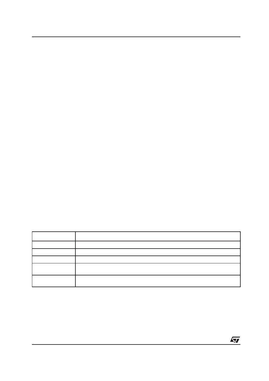
Table 11 : Compare Modes
Compare Modes
Function
Mode 0
Interrupt-only compare mode ; several compare interrupts per timer period are possible.
Mode 1
Pin toggles on each compare match ; several compare events per timer period are possible.
Mode 2
Interrupt-only compare mode ; only one compare interrupt per timer period is generated.
Mode 3
Pin set ‘1’ on match; pin reset ‘0’ on compare time overflow ; only one compare event per
timer period is generated.
Double Register Mode Two registers operate on one pin; pin toggles on each compare match ; several compare
events per timer period are possible.
相關(guān)PDF資料 |
PDF描述 |
|---|---|
| ST10F168-Q3 | 16-BIT, FLASH, 25 MHz, MICROCONTROLLER, PQFP144 |
| ST10F252M-4T3 | 16-BIT, FLASH, 40 MHz, RISC MICROCONTROLLER, PQFP100 |
| ST10F269DIETR | 16-BIT, FLASH, 32 MHz, MICROCONTROLLER, UUC |
| ST10F269Z2Q3 | 16-BIT, FLASH, 40 MHz, MICROCONTROLLER, PQFP144 |
| ST10F269Z2Q6 | 16-BIT, FLASH, 40 MHz, MICROCONTROLLER, PQFP144 |
相關(guān)代理商/技術(shù)參數(shù) |
參數(shù)描述 |
|---|---|
| ST10F168Q3 | 制造商:STMicroelectronics 功能描述:MicroController, 16-Bit, 144 Pin, Plastic, QFP |
| ST10F168-Q3 | 制造商:STMicroelectronics 功能描述:MicroController, 16-Bit, 144 Pin, Plastic, QFP |
| ST10F168-Q6 | 制造商:STMICROELECTRONICS 制造商全稱:STMicroelectronics 功能描述:16-BIT MCU WITH 256K BYTE FLASH MEMORY AND 8K BYTE RAM |
| ST10F168SQ3 | 功能描述:16位微控制器 - MCU 256K Flash 8K RAM RoHS:否 制造商:Texas Instruments 核心:RISC 處理器系列:MSP430FR572x 數(shù)據(jù)總線寬度:16 bit 最大時(shí)鐘頻率:24 MHz 程序存儲(chǔ)器大小:8 KB 數(shù)據(jù) RAM 大小:1 KB 片上 ADC:Yes 工作電源電壓:2 V to 3.6 V 工作溫度范圍:- 40 C to + 85 C 封裝 / 箱體:VQFN-40 安裝風(fēng)格:SMD/SMT |
| ST10F168SQ6 | 功能描述:16位微控制器 - MCU 256K Flash 8K RAM RoHS:否 制造商:Texas Instruments 核心:RISC 處理器系列:MSP430FR572x 數(shù)據(jù)總線寬度:16 bit 最大時(shí)鐘頻率:24 MHz 程序存儲(chǔ)器大小:8 KB 數(shù)據(jù) RAM 大小:1 KB 片上 ADC:Yes 工作電源電壓:2 V to 3.6 V 工作溫度范圍:- 40 C to + 85 C 封裝 / 箱體:VQFN-40 安裝風(fēng)格:SMD/SMT |
發(fā)布緊急采購,3分鐘左右您將得到回復(fù)。