- 您現(xiàn)在的位置:買(mǎi)賣(mài)IC網(wǎng) > PDF目錄383876 > T7536 (Lineage Power) 16-Channel Programmable Codec Chip Set(十六通道可編程編解碼器芯片組) PDF資料下載
參數(shù)資料
| 型號(hào): | T7536 |
| 廠商: | Lineage Power |
| 元件分類(lèi): | Codec |
| 英文描述: | 16-Channel Programmable Codec Chip Set(十六通道可編程編解碼器芯片組) |
| 中文描述: | 16通道可編程解碼器芯片組(十六通道可編程編解碼器芯片組) |
| 文件頁(yè)數(shù): | 31/44頁(yè) |
| 文件大小: | 772K |
| 代理商: | T7536 |
第1頁(yè)第2頁(yè)第3頁(yè)第4頁(yè)第5頁(yè)第6頁(yè)第7頁(yè)第8頁(yè)第9頁(yè)第10頁(yè)第11頁(yè)第12頁(yè)第13頁(yè)第14頁(yè)第15頁(yè)第16頁(yè)第17頁(yè)第18頁(yè)第19頁(yè)第20頁(yè)第21頁(yè)第22頁(yè)第23頁(yè)第24頁(yè)第25頁(yè)第26頁(yè)第27頁(yè)第28頁(yè)第29頁(yè)第30頁(yè)當(dāng)前第31頁(yè)第32頁(yè)第33頁(yè)第34頁(yè)第35頁(yè)第36頁(yè)第37頁(yè)第38頁(yè)第39頁(yè)第40頁(yè)第41頁(yè)第42頁(yè)第43頁(yè)第44頁(yè)
Lucent Technologies Inc.
31
Data Sheet
February 1999
Codec Chip Set
T7531A/T7536 16-Channel Programmable
Timing Characteristics
(continued)
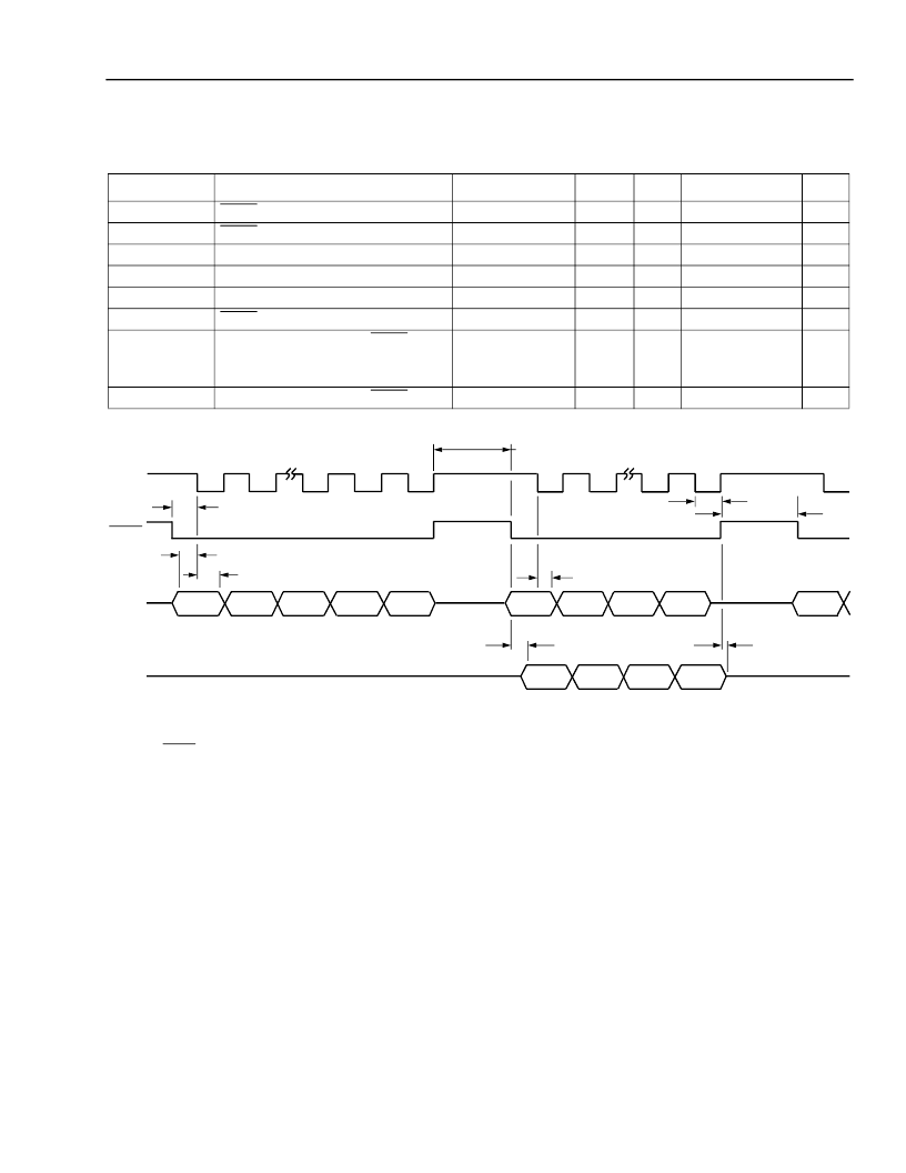
Table 17. Serial Control Port Timing
(See Figure 10.)
5-4232a (F)
Notes:
UPDI and UPCS change at the rising edge of UPCK by the microprocessor and are sampled at the falling edge of UPCK by the DSP
UPDO changes at the rising edge of UPCK by the DSP and is sampled at the falling edge of UPCK by the microprocessor.
Figure 10. Timing Diagram for Microprocessor Write/Read to/from the DSP on the Control Interface
Symbol
tCSHLSET
tCSLHHOD
tUPDIST
tUPDIHD
tUPDODEL
tUPDOHZDL
tCKCSH
Parameter
Test Conditions
—
—
—
—
C
L
= 50 pF
C
L
= 50 pF
Min
25
20 ns
25
20
—
—
Typ
—
—
—
—
—
—
Max
—
Unit
ns
—
ns
ns
ns
ns
UPCS
to UPCK Setup
UPCS
to UPCK Hold
UPDI to UPCK Setup
UPDI to UPCK Hold
UPCK to UPDO Delay
UPCS
to UPDO High-Z
Duration of UPCK and
UPCS
High:
Write Cycle
Read Cycle
Duration of UPCK and
UPCS
High
UPCK Period/2
—
—
42
34
—
—
—
1
9
9
—
—
—
—
—
—
μ
s
μ
s
μ
s
tCKCSH1
tCSHLSET
tCSLHHOD
tUPDOHZDL
0
13—1
14
15
0
13—1
14
15
tUPDIHD
DATA (16 bits)
tUPDODEL
0
1
13—2
14
15
tUPDIST
tUPDIHD
ADDRESS (16 bits)
UPDI
UPDO
UPCS
UPCK
HIGH-Z STATE
DATA (16 bits)
tCKCSH
ADDRESS
tCKCSH1
發(fā)布緊急采購(gòu),3分鐘左右您將得到回復(fù)。