- 您現(xiàn)在的位置:買賣IC網(wǎng) > PDF目錄361357 > T81L0003B (TM Technology, Inc.) 8-bit MCU PDF資料下載
參數(shù)資料
| 型號: | T81L0003B |
| 廠商: | TM Technology, Inc. |
| 英文描述: | 8-bit MCU |
| 中文描述: | 8位微控制器 |
| 文件頁數(shù): | 8/16頁 |
| 文件大小: | 100K |
| 代理商: | T81L0003B |

TE
CH
tm
T81L0003B
Multiprocessor Communications
Modes 2 and 3 have a special provision for multiprocessor communications. In these modes, 9 data bits are received.
The 9
th
one goes into RB8. Then comes a stop bit. The port can be programmed such that when the stop bit is received, the
serial port interrupt will be activated only if RB8 = ‘1’. This feature is enabled by setting bit SM2 in SCON. A way to use
this feature in multiprocessor systems is as follows: When the master processor wants to transmit a block of data to one of
several slaves, it first sends out an address byte which identifies the target slave. An address byte differs from a data byte in
that the 9th bit is ‘1’ in an address byte and ‘0’ in a data byte. With SM2 = ‘1’, no slave will be interrupted by a data byte. An
address byte, however, will interrupt all slaves, so that each slave can examine the received byte and see if it is being
addressed. The addressed slave will clear its SM2 bit and prepare to receive the data bytes that will be coming. The slaves
that weren’t being addressed leave their SM2s set and go on about their business, ignoring the coming data bytes.
SM2 has no effect in Mode 0, in Mode 1 can be used to check the validity of the stop bit. In Mode 1 reception, if
SM2 = ‘1’, the receive interrupt will not active unless a valid stop bit is received.
Serial Port Control Register
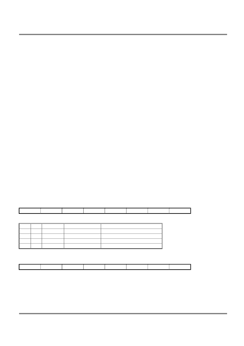
The serial port control and status register is the Special Function Register SCON, shown in Figure 11. This register
contains not only the mode selection bits, but also the 9th data bit for transmit and receive (TB8 and RB8), and the serial port
interrupt bits (TI and RI).
Baud Rates
The baud rate in Mode 0 is fixed: Mode 0 Baud Rate = Oscillator Frequency / 12. The baud rate in Mode 2 depends on
the value of bit SMOD in Special Function Register PCON. If SMOD = ‘0’ (which is the value on reset), the baud rate is 1/64
the oscillator frequency. If SMOD = ‘1’, the baud rate is 1/32 the oscillator frequency.
Mode 2 Baud Rate =2
SMOD
/64* (Oscillator Frequency)
In the T81L0006A, the baud rates in Modes 1 and 3 are determined by the Timer 1 overflow rate.
Using Timer 1 to Generate Baud Rates
When Timer 1 is used as the baud rate generator, the baud rates in Modes 1 and 3 are determined by the Timer 1 overflow
rate and the value of SMOD as follows:
Mode 1, 3 Baud Rate =2
SMOD
/32* (Timer 1 Overflow Rate)
The Timer 1 interrupt should be disabled in this application. The Timer 1 itself can be configured for either “timer” or
“counter” operation, and in any of its 3 running modes. In the most typical applications, it is configured for “timer” operation,
in the auto-reload mode (high nibble of TMOD = 0010B). In that case the baud rate is given by the formula:
Mode 1, 3 Baud Rate =2
SMOD
*(Oscillator Frequency)/ 32/12 / [256 _ (TH1)]
One can achieve very low baud rates with Timer 1 by leaving the Timer 1 interrupt enabled, and configuring the Timer to run
as a 16-bit timer (high nibble of TMOD = 0001B), and using the Timer 1 interrupt to do a 16-bit software reload.
MSB
SM0
SM1
SM2
REN
TB8
Where SM0, SM1 specify the serial port mode, as follows:
SM0 SM1
Mode
Description
Baud Rate
0
0
0
shift register
f
OSC
/ 12
0
1
1
8-bit UART
Variable
1
0
2
9-bit UART
UART F
OSC
/64 or F
OSC
/32
1
1
3
9-bit UART
Variable
Interrupt Enable Register : IE
MSB
EA
wdt
ET2
ES
ET1
EA IE.7 Disables all interrupts. If EA = 0, no interrupt will be acknowledged. If EA = 1, each interrupt source is
individually enabled or disabled by setting or clearing its enable bit.
wdt IE.6 Watchdog timer refresh flag.
ET2 IE.5 Enable or disable the Timer 2 overflow interrupt.
ES IE.4 Enable or disable the serial port interrupt.
ET1 IE.3 Enable or disable the Timer 1 overflow interrupt.
EX1 IE.2 Enable or disable External Interrupt 1.
ET0 IE.1 Enable or disable the Timer 0 overflow interrupt.
EX0 IE.0 Enable or disable External Interrupt 0.
TM Technology Inc. reserves the right
P. 8
Publication Date: NOV. 2005
to change products or specifications without notice. Revision:A
LSB
RI
RB8
TI
LSB
EX0
EX1
ET0
相關(guān)PDF資料 |
PDF描述 |
|---|---|
| T81L0003B-AD | 8-bit MCU |
| T81L0003B-AK | 8-bit MCU |
| T81L0003B-BD | 8-bit MCU |
| T81L0003B-BK | 8-bit MCU |
| T81L0006A | 8-bit A/D Type MCU |
相關(guān)代理商/技術(shù)參數(shù) |
參數(shù)描述 |
|---|---|
| T81L0003B-AD | 制造商:TMT 制造商全稱:TMT 功能描述:8-bit MCU |
| T81L0003B-AK | 制造商:TMT 制造商全稱:TMT 功能描述:8-bit MCU |
| T81L0003B-BD | 制造商:TMT 制造商全稱:TMT 功能描述:8-bit MCU |
| T81L0003B-BK | 制造商:TMT 制造商全稱:TMT 功能描述:8-bit MCU |
| T81L0006A | 制造商:TMT 制造商全稱:TMT 功能描述:8-bit A/D Type MCU |
發(fā)布緊急采購,3分鐘左右您將得到回復(fù)。