- 您現在的位置:買賣IC網 > PDF目錄98158 > TAS3218PZPR (TEXAS INSTRUMENTS INC) SPECIALTY CONSUMER CIRCUIT, PQFP100 PDF資料下載
參數資料
| 型號: | TAS3218PZPR |
| 廠商: | TEXAS INSTRUMENTS INC |
| 元件分類: | 消費家電 |
| 英文描述: | SPECIALTY CONSUMER CIRCUIT, PQFP100 |
| 封裝: | GREEN, PLASTIC, TQFP-100 |
| 文件頁數: | 38/79頁 |
| 文件大小: | 1263K |
| 代理商: | TAS3218PZPR |
第1頁第2頁第3頁第4頁第5頁第6頁第7頁第8頁第9頁第10頁第11頁第12頁第13頁第14頁第15頁第16頁第17頁第18頁第19頁第20頁第21頁第22頁第23頁第24頁第25頁第26頁第27頁第28頁第29頁第30頁第31頁第32頁第33頁第34頁第35頁第36頁第37頁當前第38頁第39頁第40頁第41頁第42頁第43頁第44頁第45頁第46頁第47頁第48頁第49頁第50頁第51頁第52頁第53頁第54頁第55頁第56頁第57頁第58頁第59頁第60頁第61頁第62頁第63頁第64頁第65頁第66頁第67頁第68頁第69頁第70頁第71頁第72頁第73頁第74頁第75頁第76頁第77頁第78頁第79頁

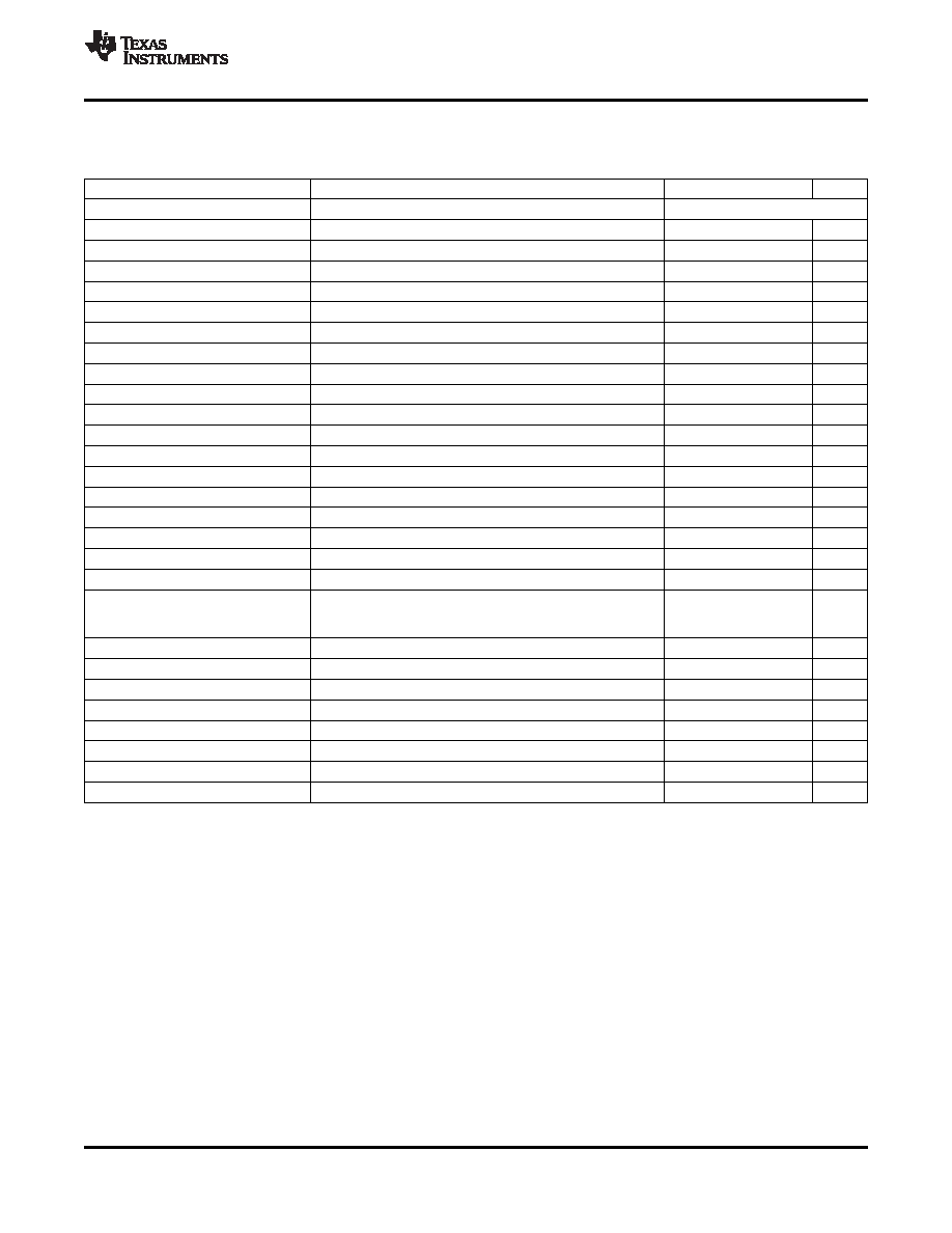
ELECTRICAL SPECIFICATIONS ANALOG SECTIONS
(1)
www.ti.com ....................................................................................................................................................................................................... SLES235 – JULY 2008
TA =25C, AVDD = 3.3 V, DVDD = 3.3 V, Fs (audio) = 48 kHz, Clock source from XTALI, AES17 filter, second order 30-kHz
low-pass filter (unless otherwise noted)
PARAMETER
TEST CONDITIONS
MIN
TYP
MAX
UNIT
Stereo MUX Input/ADC Channel
1-kHz sine wave input
Full scale input voltage (0 dB)
1
1.15
Vrms
Input common mode voltage
over recommended operating conditions
1.43
1.5
1.57
V
DNR
60-dB full-scale input applied at Line inputs, A-weighted
90
93
dBA
THD + N
1-kHz, 4-dB full-scale input
75
80
dB
PSRR
1 kHz, 100 mVpp on AVDD
51
57
dB
Channel separation
1 kHz
80
90
dB
Input resistance
14.6
18.33
22
k
Input capacitance
10
pF
DAC Channel/DAC Output
1-kHz sine wave input, load = 10 k, 10 pF
Full scale output voltage (0 dB)
0.81
0.9
Vrms
Gain error
10
%
Output common mode
over recommended operating conditions
1.43
1.5
1.57
V
DNR
60-dB full-scale input applied at Line inputs, A-weighted
95
97
dBA
THD + N
1-dBFS input, 0 dB gain
80
90
dB
PSRR
1 kHz, 100 mVpp on AVDD, VGND powered down
50
56
dB
Load capacitance
pF
Load resistance
10
k
Channel separation
81
84
dB
1-kHz sine wave input, Load = 16 , external series resistance
DAC Channel/ Headphone Output
= 16 ,
coupling capacitance = 47 F
Full scale output voltage (0 dB)
0.72
0.9
Vrms
DNR
60-dB full-scale input applied at Line inputs, A-weighted
80
90
dBA
THD + N
0-dBFS input, 0-dB gain
50
60
dB
PSRR
1 kHz, 100 mVpp on AVDD , VGND powered down
48
54
dB
Maximum output power(2)
24
mW
Load capacitance
100
pF
Load resistance
16
Channel separation
70
80
dB
(1)
When the TAS3218 is operated in slave mode, the internal analog clocks for ADC and DAC are derived from external MCLKIN input. In
this case, the analog performance will depend on MCLKIN quality (i.e., jitter, phase noise, etc.).
(2)
16- series resistor required in L and R headphone outputs for short-circuit protection.
Copyright 2008, Texas Instruments Incorporated
43
Product Folder Link(s): TAS3218
相關PDF資料 |
PDF描述 |
|---|---|
| TAS3218PZP | SPECIALTY CONSUMER CIRCUIT, PQFP100 |
| TAS5000PFB | SPECIALTY CONSUMER CIRCUIT, PQFP48 |
| TAS5000PFBG4 | SPECIALTY CONSUMER CIRCUIT, PQFP48 |
| TAS5001PFB | SPECIALTY CONSUMER CIRCUIT, PQFP48 |
| TAS5001IPFBR | SPECIALTY CONSUMER CIRCUIT, PQFP48 |
相關代理商/技術參數 |
參數描述 |
|---|---|
| TAS-3225A | 制造商:TEW 功能描述: |
| TAS-3225A 44.000KHZ | 制造商:TEW 功能描述: |
| TAS-3225J 13.56MHz }20ppm/22pF | 制造商:Tokyo Denpa 功能描述:13.560000MHz }20ppm }15ppm 22pF 3.2~2.5~0.55mm +85 -30 3.2mm 2.5mm 0.55mm Cut Tape |
| TAS-3225J 14.7456MHz }20ppm/18pF | 制造商:Tokyo Denpa 功能描述:14.745600MHz }20ppm }15ppm 18pF 3.2~2.5~0.55mm +85 -30 3.2mm 2.5mm 0.55mm Cut Tape |
| TAS-3225J 16MHz }20ppm/16pF | 制造商:Tokyo Denpa 功能描述:16.000000MHz }20ppm }15ppm 16pF 3.2~2.5~0.55mm +85 -30 3.2mm 2.5mm 0.55mm Cut Tape |
發(fā)布緊急采購,3分鐘左右您將得到回復。