- 您現(xiàn)在的位置:買(mǎi)賣(mài)IC網(wǎng) > PDF目錄373617 > TDA2030AV (意法半導(dǎo)體) 18W Hi-Fi AMPLIFIER AND 35W DRIVER PDF資料下載
參數(shù)資料
| 型號(hào): | TDA2030AV |
| 廠商: | 意法半導(dǎo)體 |
| 元件分類(lèi): | 音頻放大器 |
| 英文描述: | 18W Hi-Fi AMPLIFIER AND 35W DRIVER |
| 中文描述: | 18W高保真放大器和35W的驅(qū)動(dòng) |
| 文件頁(yè)數(shù): | 12/15頁(yè) |
| 文件大小: | 238K |
| 代理商: | TDA2030AV |
第1頁(yè)第2頁(yè)第3頁(yè)第4頁(yè)第5頁(yè)第6頁(yè)第7頁(yè)第8頁(yè)第9頁(yè)第10頁(yè)第11頁(yè)當(dāng)前第12頁(yè)第13頁(yè)第14頁(yè)第15頁(yè)
In thecase of the sawtoothin Figure25 the mean
level was increased by the TIM distortion, for a
sawtoothinthe other direction the oppositeis true.
The result is an AC signal at the output whole
peak-to-peakvalue is the TIM voltage, which can
be measured easily with an oscilloscope. If the
peak-to-peakvalue of the signal and the peak-to-
peak of the inverting sawtooth are measured,the
TIM can be found very simply from:
V
OUT
V
sawtooth
100
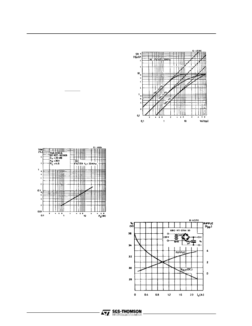
In Figure25 theexperimentalresultsareshownfor
the 30Wamplifier using the TDA2030Aas adriver
and a low-cost complementary pair. A simple RC
filter on the input of the amplifier to limit the maxi-
mumsignalslope (SS)isaneffectivewayto reduce
TIM.
TIM
=
Figure 25 :
TIM Distortion versus Output Power
The diagram of Figure 26 originated by SGS-
THOMSONcanbeusedto findtheSlew-Rate(SR)
required for a given output power or voltageand a
TIM design target.
For example if an anti-TIM filter with a cutoff at
30kHz is used and the max. peak-to-peak output
voltage is 20V then, referring to the diagram, a
Slew-Rate of 6V/
μ
s is necessaryfor 0.1%TIM.
As shown Slew-Rates of above 10V/
μ
s do not
contributeto a furtherreductionin TIM.
Slew-Ratesof 100/
μ
s arenotonlyuseless butalso
a disadvantage in Hi-Fi audio amplifiers because
they tend to turn the amplifierinto a radio receiver.
Figure 26 :
TIM Design Diagram (f
C
= 30kHz)
POWER SUPPLY
Usingmonolithicaudioamplifierwithnon-regulated
supply voltage it is important to designthe power
supply correctly. In any working case it must pro-
videasupplyvoltageless thanthe maximumvalue
fixed by the IC break-downvoltage.
It is essential to take into account all the working
conditions,inparticularmainsfluctuationsandsup-
ply voltage variations with and without load. The
TDA2030A(V
S max
=44V) isparticularlysuitablefor
substitution of the standard IC power amplifiers
(with V
S max
= 36V) for more reliableapplications.
An example, using a simple full-wave rectifier fol-
lowed by a capacitorfilter, is shown in the table 1
and in the diagramof Figure 27.
Figure27 :
DCCharacteristicsof
50W Non-regulatedSupply
TDA2030A
12/15
相關(guān)PDF資料 |
PDF描述 |
|---|---|
| TDA2030H | Single Audio Amplifier |
| TDA2030V | Single Audio Amplifier |
| TDA2030 | Single Audio Amplifier |
| TDA2030A | Insulation Putty 1 1/2 inch x 60 inch RoHS Compliant: Yes |
| TDA2030 | 14W Hi-Fi Audio Amplifier(14W Hi-Fi 音頻放大器) |
相關(guān)代理商/技術(shù)參數(shù) |
參數(shù)描述 |
|---|---|
| TDA2030AV | 制造商:STMicroelectronics 功能描述:IC AUDIO AMP 18W |
| TDA2030H | 功能描述:音頻放大器 14W Hi-Fi Audio Amp RoHS:否 制造商:STMicroelectronics 產(chǎn)品:General Purpose Audio Amplifiers 輸出類(lèi)型:Digital 輸出功率: THD + 噪聲: 工作電源電壓:3.3 V 電源電流: 最大功率耗散: 最大工作溫度: 安裝風(fēng)格:SMD/SMT 封裝 / 箱體:TQFP-64 封裝:Reel |
| TDA2030H | 制造商:STMicroelectronics 功能描述:IC AUDIO AMP 14W |
| TDA2030L-TA5-T | 制造商:UTC-IC 制造商全稱(chēng):UTC-IC 功能描述:14W HI-FI AUDIO AMPLIFIER |
| TDA2030L-TB5-T | 制造商:UTC-IC 制造商全稱(chēng):UTC-IC 功能描述:14W HI-FI AUDIO AMPLIFIER |
發(fā)布緊急采購(gòu),3分鐘左右您將得到回復(fù)。