- 您現(xiàn)在的位置:買賣IC網(wǎng) > PDF目錄373622 > TDA7400 (意法半導體) ADVANCED CAR SIGNAL PROCESSOR PDF資料下載
參數(shù)資料
| 型號: | TDA7400 |
| 廠商: | 意法半導體 |
| 英文描述: | ADVANCED CAR SIGNAL PROCESSOR |
| 中文描述: | 先進的汽車信號處理器 |
| 文件頁數(shù): | 17/28頁 |
| 文件大小: | 209K |
| 代理商: | TDA7400 |
第1頁第2頁第3頁第4頁第5頁第6頁第7頁第8頁第9頁第10頁第11頁第12頁第13頁第14頁第15頁第16頁當前第17頁第18頁第19頁第20頁第21頁第22頁第23頁第24頁第25頁第26頁第27頁第28頁
L
G
=
REF5V
Fieldstrength
voltage[STEREO]
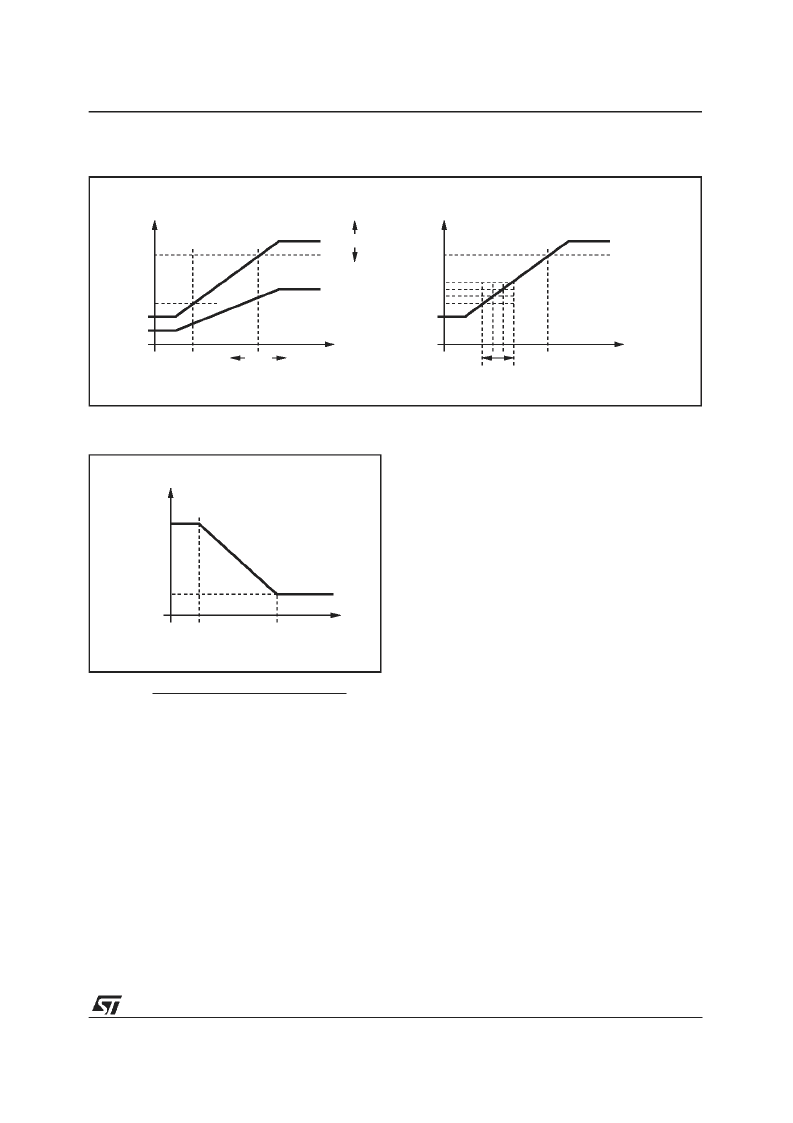
The gain can be programmed through 4 bits in
the ”Stereodecoder-Adjustment”byte.
The MONO voltage VMO (0dB channel separa-
tion)can be choosenselecting VSBL
All necessary internal reference voltages like
REF5V are derived from a bandgap circuit.
Therefore they have a temperature coefficient
near zero. This is useful if the fieldstrength signal
is alsotemperaturecompensated.
But mostIF devicesapply a LEVELvoltagewith a
TC of 3300ppm. The TDA7400D offers this TC
for the reference voltages, too. The TC is select-
able with bit D
7
of the”stereodecoderadjustment”
byte.
Highcut Control
The highcut control setup is similar to the
stereoblend control setup : the starting point
VHCH can be set with 2 bits to be 42, 50, 58 or
66% of REF5V whereas the range can be set to
be 17,22, 28 or 33% of VHCH (see fig. 21).
FUNCTIONAL DESCRIPTION OF THE NOISE-
BLANKER
In the automotive environment the MPX signal is
disturbed by spikes produced by the ignition and
for example the wiper motor. The aim of the
noiseblanker part is to cancel the audible influ-
ence of the spikes.
Therefore the output of the stereodecoderis held
at the actual voltage for a time between 22 and
38
μ
s (programmable).
The block diagram of the noiseblanker is given in
fig.17.
In a first stage the spikes must be detectedbut to
avoid a wrong triggering on high frequency
(white) noise a complex trigger control is imple-
mented. Behind the triggerstage a pulse former
generates the ”blanking” pulse. To avoid any
crosstalk to the signalpath the noiseblanker is
suppliedby his own biasing circuit.
TriggerPath
The incoming MPX signal is highpass filtered,
amplified and rectified. This second order high-
pass-filter has a cornerfrequencyof 140kHz.
The rectified signal, RECT, is lowpass filtered to
generate a signal called PEAK. Also noise with a
frequency 140kHz increases the PEAK voltage.
The resulting voltage can be adjusted by use of
the noise rectifier dischargecurrent.
The PEAKvoltage is fed to a threshold generator,
which adds to the PEAK voltage a DC depend-
ent threshold VTH. Both signals, RECT and
INTERNAL
VOLTAGES
t
D97AU639
VSBL
REF 5V
SETUP OF VST
INTERNAL
VOLTAGES
t
REF 5V
SETUP OF VMO
LEVEL
LEVEL INTERN
FIELDSTRENGHT VOLTAGE
VST
VMO
LEVEL INTERN
33%
VSBL
VST
VMO
FIELDSTRENGHT VOLTAGE
Figure 15. RelationBetweenInternaland ExternalLEVELVoltageandSetup ofStereoblend
LOWPASS
TIME CONSTANT
D97AU640
τ
Deemp
FIELDSTRENGHT
VHCH
VHCL
3
τ
Deemp
Figure 16. HighcutCharacteristics
TDA7400
17/28
相關PDF資料 |
PDF描述 |
|---|---|
| TDA7401 | DIGITALLY CONTROLLED AUDIO PROCESSOR WITH LOUDSPEAKERS EQUALIZER |
| TDA7401D | DIGITALLY CONTROLLED AUDIO PROCESSOR WITH LOUDSPEAKERS EQUALIZER |
| TDA7402 | CARRADIO SIGNAL PROCESSOR |
| TDA7403 | BASIC SIGNAL PROCESSOR |
| TDA7403D | BASIC SIGNAL PROCESSOR |
相關代理商/技術參數(shù) |
參數(shù)描述 |
|---|---|
| TDA7400D | 制造商:STMICROELECTRONICS 制造商全稱:STMicroelectronics 功能描述:ADVANCED CAR SIGNAL PROCESSOR |
| TDA7400DTR | 功能描述:音頻 DSP ADV CAR SGNL PROCESR RoHS:否 制造商:Texas Instruments 工作電源電壓: 電源電流: 工作溫度范圍: 安裝風格: 封裝 / 箱體: 封裝:Tube |
| TDA7401 | 功能描述:音頻 DSP Digital Audio Proc RoHS:否 制造商:Texas Instruments 工作電源電壓: 電源電流: 工作溫度范圍: 安裝風格: 封裝 / 箱體: 封裝:Tube |
| TDA7401013TR | 功能描述:音頻 DSP Digital Audio Proc RoHS:否 制造商:Texas Instruments 工作電源電壓: 電源電流: 工作溫度范圍: 安裝風格: 封裝 / 箱體: 封裝:Tube |
| TDA7401D | 功能描述:音頻 DSP Digital Audio Proc RoHS:否 制造商:Texas Instruments 工作電源電壓: 電源電流: 工作溫度范圍: 安裝風格: 封裝 / 箱體: 封裝:Tube |
發(fā)布緊急采購,3分鐘左右您將得到回復。