- 您現(xiàn)在的位置:買賣IC網(wǎng) > PDF目錄373622 > TDA7400 (意法半導(dǎo)體) ADVANCED CAR SIGNAL PROCESSOR PDF資料下載
第1頁第2頁第3頁第4頁第5頁第6頁第7頁第8頁第9頁第10頁第11頁第12頁第13頁第14頁第15頁第16頁第17頁當(dāng)前第18頁第19頁第20頁第21頁第22頁第23頁第24頁第25頁第26頁第27頁第28頁
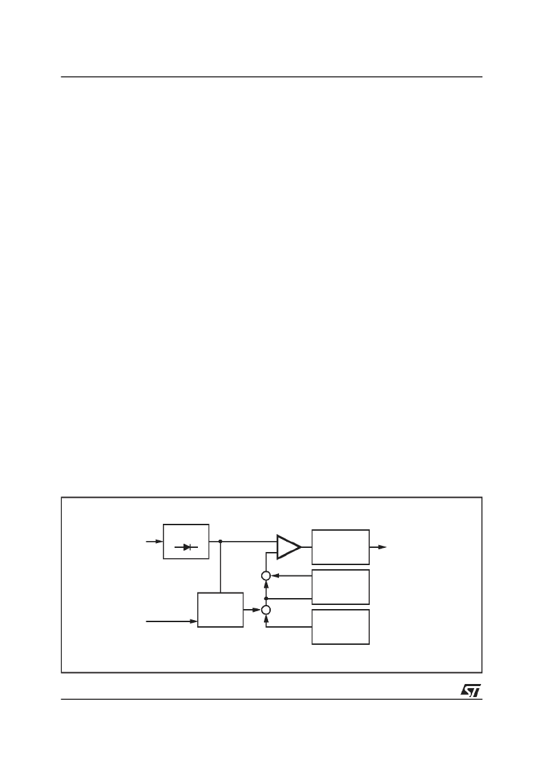
PEAK+VTH are fed to a comparator which trig-
gers a re-triggerable monoflop. The monoflop’s
output activates the sample-and-hold circuits in
the signalpathfor selectedduration.
Automatic Noise Controlled Threshold Adjust-
ment (ATC)
There are mainly two independentpossibilities for
programmingthe trigger threshold:
a the low thresholdin 8 steps (bits D
0
to D
2
of
the noiseblankerbyte)
b the noise adjustedthreshold in 4 steps
(bits D
3
andD
4
of the noiseblankerbyte,
see fig.14).
The low threshold is active in combination with a
good MPX signal without any noise; the PEAK
voltage is less than 1V. The sensitivity in this op-
eration is high.
If the MPX signal is noisy the PEAK voltage in-
creases due to the higher noise, which is also
rectified. With increasing of the PEAK voltage the
trigger threshold increases, too.
gain is programmablein 4 steps(see fig. ...).
This particular
AUTOMATIC THRESHOLD CONTROL MECHA-
NISM
Automatic
StereoblendVoltage
Besides the noise controlled threshold adjust-
ment there is an additional possibility for influenc-
ing the trigger threshold. It is depending on the
stereoblendcontrol.
The point where the MPX signal starts to become
Threshold
Control
by
the
noisy is fixed by the RF part. Therefore also the
starting point of the normal noise-controlled trig-
ger adjustment is fixed (fig. 11). In some cases
the behaviour of the noiseblanker can be im-
proved by increasing the threshold even in a re-
gion of higher fieldstrength. Sometimes a wrong
triggering occures for the MPX signal often shows
distortion in this range which can be avoided
even if usinga low threshold.
Because of the overlap of this range and the
range of the stereo/monotransition it can be con-
trolled by stereoblend. This threshold increase is
programmable in 3 steps or switched off with bits
D
0
and D
1
of the fieldstrengthcontrolbyte.
Over DeviationDetector
If the system is tuned to stations with a high de-
viation the noiseblanker can trigger on the higher
frequencies of the modulation. To avoid this
wrong behaviour, which causes noise in the out-
put signal, the noiseblankeroffers a deviationde-
pendent thresholdadjustment.
By rectifying the MPX signal a further signal rep-
resenting the actual deviation is obtained. It is
used to increase the PEAK voltage. Offset and
gain of this circuit are programmable in 3 steps
with the bits D
6
and D
7
of the stereodecoderbyte
(the first step turns off the detector,see fig. 15).
FUNCTIONAL DESCRIPTION OF THE MULTI-
PATH DETECTOR
Using the internal multipath detector the audible
effects of a multipathcondition can be minimized.
A multipath condition is detected by rectifying the
19kHz spectrumin the fieldstrengthsignal.
An external capacitor is used to define the attack
and decay times (see block diagram fig. 23). the
+
-
RECTIFIER
LOWPASS
RECT
+
+
THRESHOLD
GENERATOR
VTH
PEAK
ADDITIONAL
THRESHOLD
CONTROL
MONOFLOP
HOLDN
MPX
D98AU856
MPX
CONTROL
Figure 17. BlockDiagramoftheNoiseblanker
TDA7400
18/28
相關(guān)PDF資料 |
PDF描述 |
|---|---|
| TDA7401 | DIGITALLY CONTROLLED AUDIO PROCESSOR WITH LOUDSPEAKERS EQUALIZER |
| TDA7401D | DIGITALLY CONTROLLED AUDIO PROCESSOR WITH LOUDSPEAKERS EQUALIZER |
| TDA7402 | CARRADIO SIGNAL PROCESSOR |
| TDA7403 | BASIC SIGNAL PROCESSOR |
| TDA7403D | BASIC SIGNAL PROCESSOR |
相關(guān)代理商/技術(shù)參數(shù) |
參數(shù)描述 |
|---|---|
| TDA7400D | 制造商:STMICROELECTRONICS 制造商全稱:STMicroelectronics 功能描述:ADVANCED CAR SIGNAL PROCESSOR |
| TDA7400DTR | 功能描述:音頻 DSP ADV CAR SGNL PROCESR RoHS:否 制造商:Texas Instruments 工作電源電壓: 電源電流: 工作溫度范圍: 安裝風(fēng)格: 封裝 / 箱體: 封裝:Tube |
| TDA7401 | 功能描述:音頻 DSP Digital Audio Proc RoHS:否 制造商:Texas Instruments 工作電源電壓: 電源電流: 工作溫度范圍: 安裝風(fēng)格: 封裝 / 箱體: 封裝:Tube |
| TDA7401013TR | 功能描述:音頻 DSP Digital Audio Proc RoHS:否 制造商:Texas Instruments 工作電源電壓: 電源電流: 工作溫度范圍: 安裝風(fēng)格: 封裝 / 箱體: 封裝:Tube |
| TDA7401D | 功能描述:音頻 DSP Digital Audio Proc RoHS:否 制造商:Texas Instruments 工作電源電壓: 電源電流: 工作溫度范圍: 安裝風(fēng)格: 封裝 / 箱體: 封裝:Tube |
發(fā)布緊急采購,3分鐘左右您將得到回復(fù)。