- 您現(xiàn)在的位置:買賣IC網(wǎng) > PDF目錄98196 > TDA7444 (STMICROELECTRONICS) SPECIALTY CONSUMER CIRCUIT, PDIP28 PDF資料下載
參數(shù)資料
| 型號(hào): | TDA7444 |
| 廠商: | STMICROELECTRONICS |
| 元件分類: | 消費(fèi)家電 |
| 英文描述: | SPECIALTY CONSUMER CIRCUIT, PDIP28 |
| 封裝: | DIP-28 |
| 文件頁(yè)數(shù): | 6/18頁(yè) |
| 文件大?。?/td> | 211K |
| 代理商: | TDA7444 |
第1頁(yè)第2頁(yè)第3頁(yè)第4頁(yè)第5頁(yè)當(dāng)前第6頁(yè)第7頁(yè)第8頁(yè)第9頁(yè)第10頁(yè)第11頁(yè)第12頁(yè)第13頁(yè)第14頁(yè)第15頁(yè)第16頁(yè)第17頁(yè)第18頁(yè)

- DELAY specifies the delay value in ms for S
channel.
VMax (fig. 5)
Input channels: L, R, C, S
Output channels: L, R
The VMax 3D algorithm converts the ProLogic
output into two channels. It uses head related
transfer functions (HRTFs) to create spatial
sound impression using two speakers. Using this
technology, listeners are given the auditory illu-
sion that they are immersed in an enveloping
sound field. This is done by filtering the input
audio stream to compensate for the speaker talks
to both ears, as does left speakers. The posi-
tional encoding is then obtained by filtering the in-
put signal with the appropriate HRTF to give the
desired positional information.
SRS TruSurround (fig. 5)
Input channels: L, R, C, S
Output channels: L, R
SRS TruSurround uses HRTF based frequency
tailoring of (L-R) difference signals to extend the
sound image out past the physical boundaries of
the speaker placements.
TruSurround applies HRTF frequency tailoring to
surround channel information.
These rear channel HRTF curves have much
greater peak to valley differences and centre fre-
quencies. These were chosen to cause rear
channel "difference" signals to "virtualize" farther
behind the listener and directed to a different vir-
tual position as compared to front channel sig-
nals.
Information that is equal (L+R) in the rear sur-
round channels is processed by an identical
HRTF curve but mixed in at a much lower
amount. This HRTF processing of equal (L+R)
signals was again used to virtualize information to
the rear of the listener.
SRS 3D Stereo (fig. 6)
Input channels: L, R
Output channels: L, R
The SRS 3D Stereo algorithm enlarges the sound
field of the classic stereo source processing the
signal in such a manner that the spatial cues lost
in the record/playback process are restored.
Since the human hearing system is involved and
is actually part of the loop, its transfer function is
made part of the system transfer function.
At the same time, SRS 3D Stereo system proc-
essing avoids an objectionable build-up of fre-
quencies of increased phase sensitivity and is ef-
fective over a wide area so that the listener is not
restricted to a fixed listening position between the
two speakers.
The register CENTER and SPACE set the gain
levels.
SRS 3D Mono (fig. 6)
Input channels: L, R
Output channels: L, R
SRS 3D Mono is the previous algorithm counter-
part for a mono signal such as TV sound.
Input signal passes through two banks of 3 all-
pass filters, originating two signals with one
shifted 90° relative to the other (equivalent to L+R
and L-R).
These signals are then processed by a filter chain
similar to that one used for SRS 3D Stereo.
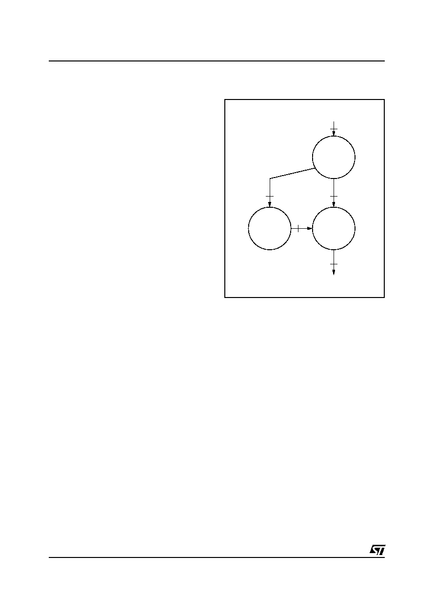
Delay (fig. 7)
Input channels: L, R
Output channels: L, R
The stereo input signal is downmixed into a
mono signal before being delayed of the DELAY
value. Then both signals are mixed according to
the DELAY_RATIO value: 0% selects the original
signal and 100% selects the delajed signal.
Loudness
LOUDNESS=
LOUDNESS_ON
Volume
Control
2
3
D98AU901
Equalizer
LOUDNESS=
LOUDNESS_OFF
4
3
4
Figure 8. Audio processor algorithms
selection
TDA7444 - TDA7444D
14/18
相關(guān)PDF資料 |
PDF描述 |
|---|---|
| TDA7444D | SPECIALTY CONSUMER CIRCUIT, PDSO28 |
| TDA7445D | SPECIALTY CONSUMER CIRCUIT, PDSO28 |
| TDA7445 | SPECIALTY CONSUMER CIRCUIT, PDIP28 |
| TDA7448 | 6 CHANNEL(S), VOLUME CONTROL CIRCUIT, PDSO20 |
| TDA744813TR | 6 CHANNEL(S), VOLUME CONTROL CIRCUIT, PDSO20 |
相關(guān)代理商/技術(shù)參數(shù) |
參數(shù)描述 |
|---|---|
| TDA7448 | 功能描述:音頻放大器 6 Ch Volume CNTRL 0 to -79dB 1.0dB CNT RoHS:否 制造商:STMicroelectronics 產(chǎn)品:General Purpose Audio Amplifiers 輸出類型:Digital 輸出功率: THD + 噪聲: 工作電源電壓:3.3 V 電源電流: 最大功率耗散: 最大工作溫度: 安裝風(fēng)格:SMD/SMT 封裝 / 箱體:TQFP-64 封裝:Reel |
| TDA7448_04 | 制造商:STMICROELECTRONICS 制造商全稱:STMicroelectronics 功能描述:6 CHANNEL VOLUME CONTROLLER |
| TDA744813TR | 功能描述:音頻放大器 6 Ch Volume CNTRL 0 to -79dB 1.0dB CNT RoHS:否 制造商:STMicroelectronics 產(chǎn)品:General Purpose Audio Amplifiers 輸出類型:Digital 輸出功率: THD + 噪聲: 工作電源電壓:3.3 V 電源電流: 最大功率耗散: 最大工作溫度: 安裝風(fēng)格:SMD/SMT 封裝 / 箱體:TQFP-64 封裝:Reel |
| TDA7448-EVB | 功能描述:音頻 IC 開發(fā)工具 Eval Brd for TDA7448 RoHS:否 制造商:Texas Instruments 產(chǎn)品:Evaluation Kits 類型:Audio Amplifiers 工具用于評(píng)估:TAS5614L 工作電源電壓:12 V to 38 V |
| TDA7449 | 功能描述:音頻 DSP Tone Control Digital RoHS:否 制造商:Texas Instruments 工作電源電壓: 電源電流: 工作溫度范圍: 安裝風(fēng)格: 封裝 / 箱體: 封裝:Tube |
發(fā)布緊急采購(gòu),3分鐘左右您將得到回復(fù)。