- 您現(xiàn)在的位置:買賣IC網(wǎng) > PDF目錄373630 > TEA7092 (意法半導(dǎo)體) TELEPHONE ANALOG FRONT END PDF資料下載
參數(shù)資料
| 型號: | TEA7092 |
| 廠商: | 意法半導(dǎo)體 |
| 英文描述: | TELEPHONE ANALOG FRONT END |
| 中文描述: | 電話模擬前端 |
| 文件頁數(shù): | 28/57頁 |
| 文件大小: | 574K |
| 代理商: | TEA7092 |
第1頁第2頁第3頁第4頁第5頁第6頁第7頁第8頁第9頁第10頁第11頁第12頁第13頁第14頁第15頁第16頁第17頁第18頁第19頁第20頁第21頁第22頁第23頁第24頁第25頁第26頁第27頁當(dāng)前第28頁第29頁第30頁第31頁第32頁第33頁第34頁第35頁第36頁第37頁第38頁第39頁第40頁第41頁第42頁第43頁第44頁第45頁第46頁第47頁第48頁第49頁第50頁第51頁第52頁第53頁第54頁第55頁第56頁第57頁
35
36
-1
26
19
Ip
3
30
TEA7092
Iear
C24
Iear
EAR+
EAR-
Rear Symmetric or
Asymmetric Use
C11
RECIN
V
CC
R10
Ip +Iear
I
L
+
C8
I
L
- (Ip + Iear)
V
L
V
S
R12
R11a/b
V
L
(3)
A
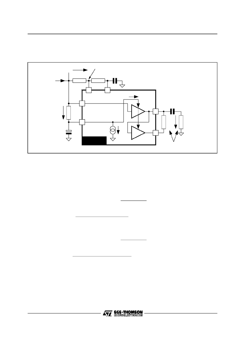
Figure43
II - SPEECHFEATURES
(continued)
II.5 - Receive Channel
(continued)
With thisprinciple the maximumoutput voltageat Pin EAR+ (Pin35) and PinEAR- (Pin 36), dependingon
the application,is limitedin currentand in voltagein the followingway : R11= R11a + R11b
I
P
= 1.3mA at I
L
= 20mA
I
P
= 1.7mA at I
L
= 60mA (see Figure 21).
V
RECIN
= V
L
(3) + R11x (I
L
- I
P
- I
EAR
) and V
CC
= V
RECIN
- R10 x (I
P
+ I
EAR
)
- In asymmetricuse; Earphone(R
EAR
) connectedon Pin EAR+ (Pin 35).
V
CC
= 2 x V
EAR(peak)(Max.)
+ 0.4
V
EAR
(
RMS
)
=π
R
EAR
I
EAR
√
2
V
EAR(RMS) (Max.)
inV
RMS
:
V
EAR(RMS) (Max.)
=
π
R
EAR
√
2
(
2
π
R
EAR
+
R10
+
R11
)
[V
L
+
R11
I
L
(
R10
+
R11
)
I
P
0.4]
- In symmetric use; Earphone (R
EAR
) connectedbetween Pin EAR+ (Pin 35) & Pin EAR- (Pin 36).
V
CC
= V
EAR (peak)(Max.)
+ 0.2
V
EAR
(
RMS
)
=
π
R
EAR
I
EAR
2
√
2
V
EAR(RMS) (Max.)
inV
RMS
:
V
EAR(RMS) (Max.)
=
π
R
EAR
√
2
(π
R
EAR
+
2
(
R10
+
R11
))
[V
L
+
R11
I
L
(
R10
+
R11
)
I
P
0.2]
Notes :
1. In few applications, at low line current (I
L
< 20mA) and depending on the DC voltage at
Pin V
L
(Pin 3), the absolute minimum value of V
CC
, 2V, should be taken into account in the
calculation of V
EAR(RMS)(Max.)
. This limitation happens if : I
L
= 20mA, R12 = 68k
and R10 =
1200
(compleximpedanceDC value).
2. Usually, when the impedance of a transducer, Rear, increases,the efficiencyof the transducer
in dBSPL/V decreases. The receive gain is adapted to the earphone impedance to offsetthis
transducer’sefficiencychange,sothatthe completeacousticalgainof thereceivepathremains
constant.
TEA7092 - TELEPHONE SET INTEGRATED CIRCUIT
28/57
相關(guān)PDF資料 |
PDF描述 |
|---|---|
| TEA7092TQ | TELEPHONE ANALOG FRONT END |
| TEA7092TQT | TELEPHONE ANALOG FRONT END |
| TEA7530DP | MONITOR AMPLIFIER |
| TEA7530FP | MONITOR AMPLIFIER |
| TEA7530 | Monitor Amplifier(監(jiān)聽放大器) |
相關(guān)代理商/技術(shù)參數(shù) |
參數(shù)描述 |
|---|---|
| TEA7092TQ | 制造商:STMicroelectronics 功能描述:SPEECH NETWORK ADVANCED 46DB 44TQFP - Trays |
| TEA7092TQT | 制造商:STMicroelectronics 功能描述:SPEECH NETWORK ADVANCED 46DB 44TQFP - Tape and Reel |
| TEA7530 | 制造商:STMICROELECTRONICS 制造商全稱:STMicroelectronics 功能描述:MONITOR AMPLIFIER |
| TEA7530DP | 制造商:STMICROELECTRONICS 制造商全稱:STMicroelectronics 功能描述:MONITOR AMPLIFIER |
| TEA7530FP | 制造商:STMICROELECTRONICS 制造商全稱:STMicroelectronics 功能描述:MONITOR AMPLIFIER |
發(fā)布緊急采購,3分鐘左右您將得到回復(fù)。