- 您現(xiàn)在的位置:買賣IC網(wǎng) > PDF目錄383953 > TLC32041I (Texas Instruments, Inc.) ANALOG INTERFACE CIRCUITS PDF資料下載
參數(shù)資料
| 型號(hào): | TLC32041I |
| 廠商: | Texas Instruments, Inc. |
| 英文描述: | ANALOG INTERFACE CIRCUITS |
| 中文描述: | 模擬接口電路 |
| 文件頁(yè)數(shù): | 21/33頁(yè) |
| 文件大小: | 453K |
| 代理商: | TLC32041I |
第1頁(yè)第2頁(yè)第3頁(yè)第4頁(yè)第5頁(yè)第6頁(yè)第7頁(yè)第8頁(yè)第9頁(yè)第10頁(yè)第11頁(yè)第12頁(yè)第13頁(yè)第14頁(yè)第15頁(yè)第16頁(yè)第17頁(yè)第18頁(yè)第19頁(yè)第20頁(yè)當(dāng)前第21頁(yè)第22頁(yè)第23頁(yè)第24頁(yè)第25頁(yè)第26頁(yè)第27頁(yè)第28頁(yè)第29頁(yè)第30頁(yè)第31頁(yè)第32頁(yè)第33頁(yè)
TLC32040C, TLC32040I, TLC32041C, TLC32041I
ANALOG INTERFACE CIRCUITS
SLAS014E – SEPTEMBER 1987 – REVISED MAY 1995
21
POST OFFICE BOX 655303
DALLAS, TEXAS 75265
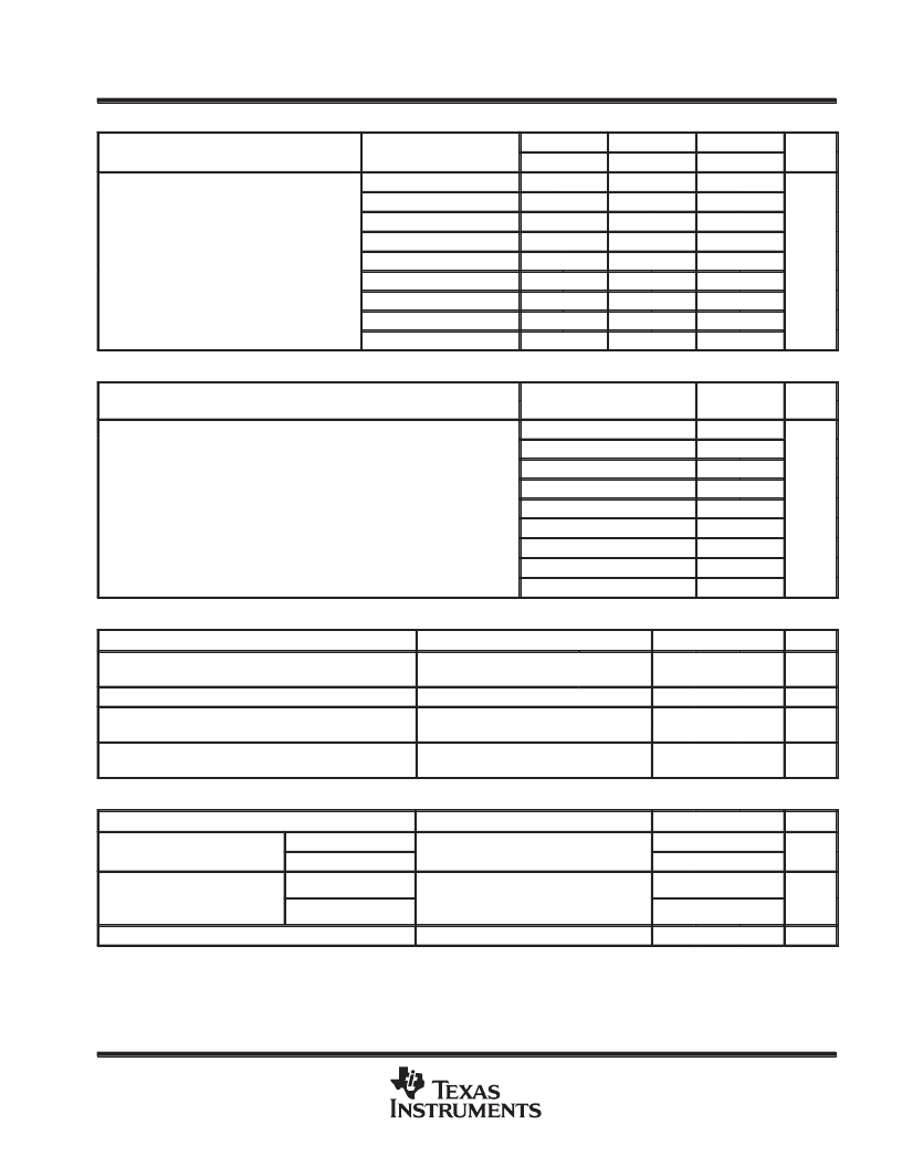
A/D channel signal-to-distortion ratio
PARAMETER
TEST CONDITIONS
(see Note 7)
Av = 1
MIN
58
Av = 2
MIN
>58§
Av = 4
MIN
>58§
>58§
UNIT
MAX
MAX
MAX
VI = –6 dB to –0.1 dB
VI = –12 dB to –6 dB
VI = –18 dB to –12 dB
VI = –24 dB to –18 dB
VI = –30 dB to –24 dB
VI = –36 dB to –30 dB
VI = –42 dB to –36 dB
VI = –48 dB to –42 dB
VI = –54 dB to –48 dB
58
58
56
58
58
50
56
58
A/D channel signal-to-distortion ratio
44
50
56
dB
38
44
50
32
38
44
26
20
32
26
38
32
D/A channel signal-to-distortion ratio
PARAMETER
TEST CONDITIONS
(see Note 7)
MIN
MAX
UNIT
VI = –6 dB to 0 dB
VI = –12 dB to –6 dB
VI = –18 dB to –12 dB
VI = –24 dB to –18 dB
VI = –30 dB to –24 dB
VI = –36 dB to –30 dB
VI = –42 dB to –36 dB
VI = –48 dB to –42 dB
VI = –54 dB to –48 dB
58
58
56
50
D/A channel signal-to-distortion ratio
44
dB
38
32
26
20
gain and dynamic range
PARAMETER
TEST CONDITIONS
MIN
TYP
MAX
UNIT
Absolute transmit gain tracking error
while transmitting into 600
Absolute receive gain tracking error
–48-dB to 0-dB signal range,
See Note 8
±
0.05
±
0.15
dB
–48-dB to 0-dB signal range,
See Note 8
±
0.05
±
0.15
dB
Absolute gain of the A/D channel
Signal input is a –0.5-dB,
1-kHz sinewave
0.2
dB
Absolute gain of the D/A channel
Signal input is a 0-dB,
1-kHz sinewave
–0.3
dB
power supply rejection and crosstalk attenuation
PARAMETER
TEST CONDITIONS
MIN
TYP
MAX
UNIT
VCC+ or VCC– supply voltage
rejection ratio, receive channel
f = 0 to 30 kHz
Idle channel, supply signal at 200 mV p-p
measured at DR (ADC output)
30
dB
f = 30 kHz to 50 kHz
45
VCC+ or VCC– supply voltage
rejection ratio transmit channel
rejection ratio, transmit channel
(single ended)
f = 0 to 30 kHz
Idle channel, supply signal at 200 mV p-p
measured at OUT+
30
dB
f = 30 kHz to 50 kHz
45
Crosswalk attenuation, transmit-to-receive (single ended)
Av is the programmable gain of the input amplifier.
All typical values are at TA = 25
°
C.
§A value >58 is overrange and signal clipping occurs.
NOTES:
7. The test condition Vin is a 1-kHz input signal with an 8-kHz conversion rate (0 dB relative to Vref). The load impedance for the DAC
is 600
.
8. Gain tracking is relative to the absolute gain at 1 kHz and 0 dB (0 dB relative to Vref).
80
dB
相關(guān)PDF資料 |
PDF描述 |
|---|---|
| TLC32040M | ANALOG INTERFACE CIRCUIT |
| TLC32040MFK | ANALOG INTERFACE CIRCUIT |
| TLC32040MJ | ANALOG INTERFACE CIRCUIT |
| TLC32044C | VOICE-BAND ANALOG INTERFACE CIRCUITS |
| TLC32045IN | VOICE-BAND ANALOG INTERFACE CIRCUITS |
相關(guān)代理商/技術(shù)參數(shù) |
參數(shù)描述 |
|---|---|
| TLC32041IN | 制造商:TI 制造商全稱:Texas Instruments 功能描述:ANALOG INTERFACE CIRCUITS |
| TLC32042EFN | 制造商:Rochester Electronics LLC 功能描述: |
| TLC32044 | 制造商:TI 制造商全稱:Texas Instruments 功能描述:VOICE-BAND ANALOG INTERFACE CIRCUITS |
| TLC32044 WAF | 制造商:Rochester Electronics LLC 功能描述: |
| TLC32044_3 WAF | 制造商:Rochester Electronics LLC 功能描述: |
發(fā)布緊急采購(gòu),3分鐘左右您將得到回復(fù)。