- 您現(xiàn)在的位置:買賣IC網(wǎng) > PDF目錄385933 > TLS24310 (Texas Instruments, Inc.) Magnetoresistive/Thin-Film Read/Write Preamplifiers(10通道磁阻/薄膜讀/寫用前置放大器) PDF資料下載
參數(shù)資料
| 型號(hào): | TLS24310 |
| 廠商: | Texas Instruments, Inc. |
| 英文描述: | Magnetoresistive/Thin-Film Read/Write Preamplifiers(10通道磁阻/薄膜讀/寫用前置放大器) |
| 中文描述: | 磁阻/薄膜讀/寫前置放大器(10通道磁阻/薄膜讀/寫用前置放大器) |
| 文件頁數(shù): | 17/31頁 |
| 文件大?。?/td> | 676K |
| 代理商: | TLS24310 |
第1頁第2頁第3頁第4頁第5頁第6頁第7頁第8頁第9頁第10頁第11頁第12頁第13頁第14頁第15頁第16頁當(dāng)前第17頁第18頁第19頁第20頁第21頁第22頁第23頁第24頁第25頁第26頁第27頁第28頁第29頁第30頁第31頁
TLS24308, TLS24310, TLS24318, TLS24320
8- AND 10-CHANNEL MAGNETORESISTIVE/THIN-FILM
READ/WRITE PREAMPLIFIERS
SQHS009 – JANUARY 1996
17
POST OFFICE BOX 655303
DALLAS, TEXAS 75265
fault switching
Fault-switching characteristics are provided using the following assumptions:
If the nongrounded side of the MR sensor becomes grounded, the head voltage diminishes due to a
decrease in the head resistance. This condition should be reported and prevented.
If the MR-sensor voltage rises to the thermal-asperity threshold, the voltage across the MR stripe rises
rapidly. This condition should be reported as a fault.
For a complete listing of optional functions, see Table 1.
fault-electrical characteristics,
L
I(TF)
= 180 nH, R
I(TF)
= 15
, f
I(W)
= 1 MHz to 65 MHz,
I
I(BIAS)
= 7 mA to 17 mA, R
(MR)
= 10
to 40
,
C
L
= 12 pF, V
IT
= 0.5 V
CC
PARAMETER
TEST CONDITIONS
MIN
3.6
TYP
3.8
MAX
4.0
UNIT
V
Vhys
Low VCCthreshold voltage (hysteresis)
Low VCC threshold voltage (hysteresis)
Fault detected
Fault removed
3.9
4.1
4.3
V
VIT(short)
VIT(open)
MR-head short threshold voltage
Fault detected
50
mV
MR-head open threshold voltage
Fault detected
R(MR) = 20
,
II(BIAS) = 16 mA measured
at RDX/RDY
750
mV
VIT
Thermal-asperity detect threshold voltage,
base to peak
390
460
530
mV
fault-switching characteristics, L
I(TF)
= 180 nH, R
I(TF)
= 15
, f
I(W)
= 1 MHz to 65 MHz,
I
I(BIAS)
= 7 mA to 17 mA, R
(MR)
= 10
to 40
,
C
L
= 12 pF, V
IT
= 0.5 V
CC
PARAMETER
TEST CONDITIONS
MIN
TYP
0.1
MAX
0.2
UNIT
μ
s
μ
s
MHz
μ
s
μ
s
μ
s
tt
Transition time thermal asperity detect
Transition time, thermal-asperity detect
Safe to unsafe
Unsafe to safe
0.2
0.4
f(WDX/WDY)
Frequency, WDX/WDY for safe condition
1
Transition time, WDX/WDY frequency low
detect
Safe to unsafe
0.6
2.0
3.6
tt
Unsafe to safe
FF disabled
FF enabled
1.1
2.6
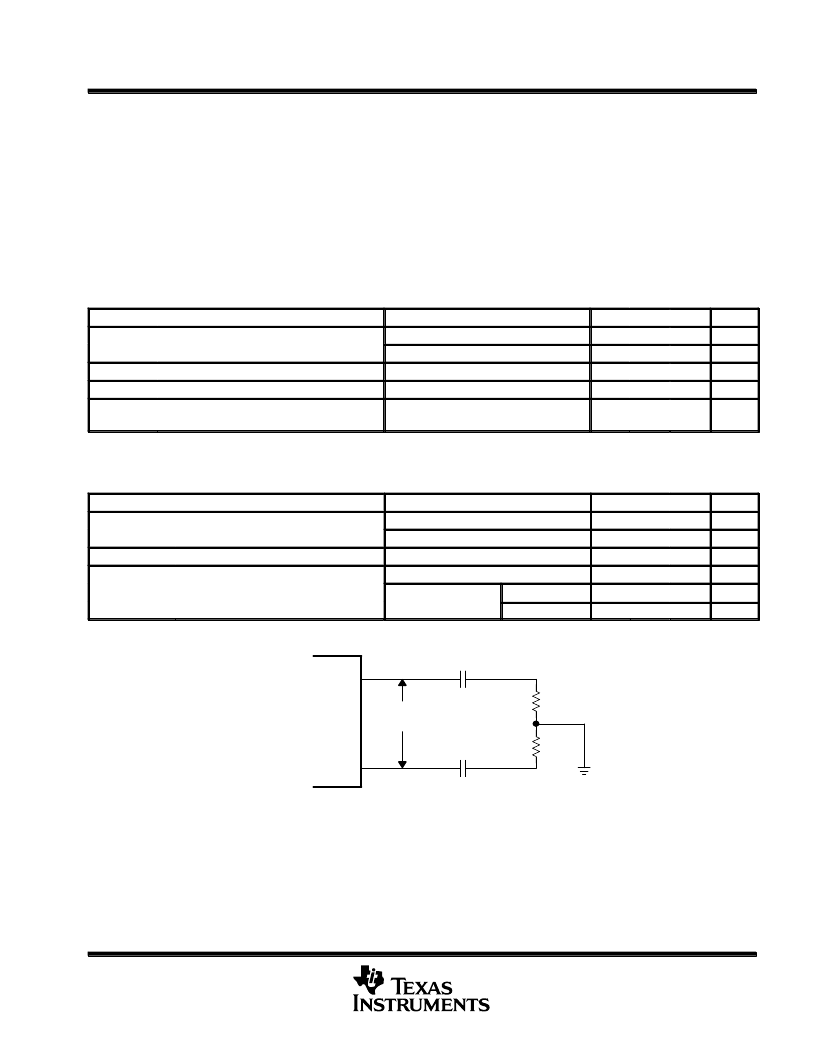
2.2 k
2.2 k
1000 pF
1000 pF
Measurement
Point
RDX
RDY
Figure 1. Read-Output-Measurement Circuit
相關(guān)PDF資料 |
PDF描述 |
|---|---|
| TLS24318 | Magnetoresistive/Thin-Film Read/Write Preamplifiers(8通道磁阻/薄膜讀/寫用前置放大器) |
| TLS24320 | Magnetoresistive/Thin-Film Read/Write Preamplifiers(10通道磁阻/薄膜讀/寫用前置放大器) |
| TLSU163 | TLSU163 |
| TLSU163F | TLSU163 |
| TLSU164 | TLSU163 |
相關(guān)代理商/技術(shù)參數(shù) |
參數(shù)描述 |
|---|---|
| TLS245 | 制造商:Texas Instruments 功能描述: |
| TLS24M554DBT | 制造商:Texas Instruments 功能描述:24M554DBT |
| TLS2501DZQLRG1 | 制造商:Texas Instruments 功能描述: |
| TLS251 | 制造商:未知廠家 制造商全稱:未知廠家 功能描述:TLG251, TLY251, TLO251, TLS251 |
| TLS255K100C1A | 制造商:CORNELL DUBILIER ELECTRONICS 功能描述:Cap Tant Wet 2.5uF 100V 10% (5.56 X 15.45mm) Axial |
發(fā)布緊急采購(gòu),3分鐘左右您將得到回復(fù)。