- 您現(xiàn)在的位置:買賣IC網(wǎng) > PDF目錄98252 > TLV320ADC3101IRGER320 (TEXAS INSTRUMENTS INC) SPECIALTY CONSUMER CIRCUIT, PQCC24 PDF資料下載
參數(shù)資料
| 型號(hào): | TLV320ADC3101IRGER320 |
| 廠商: | TEXAS INSTRUMENTS INC |
| 元件分類: | 消費(fèi)家電 |
| 英文描述: | SPECIALTY CONSUMER CIRCUIT, PQCC24 |
| 封裝: | 4 X 4 MM, GREEN, PLASTIC, VQFN-24 |
| 文件頁(yè)數(shù): | 11/83頁(yè) |
| 文件大?。?/td> | 1338K |
| 代理商: | TLV320ADC3101IRGER320 |
第1頁(yè)第2頁(yè)第3頁(yè)第4頁(yè)第5頁(yè)第6頁(yè)第7頁(yè)第8頁(yè)第9頁(yè)第10頁(yè)當(dāng)前第11頁(yè)第12頁(yè)第13頁(yè)第14頁(yè)第15頁(yè)第16頁(yè)第17頁(yè)第18頁(yè)第19頁(yè)第20頁(yè)第21頁(yè)第22頁(yè)第23頁(yè)第24頁(yè)第25頁(yè)第26頁(yè)第27頁(yè)第28頁(yè)第29頁(yè)第30頁(yè)第31頁(yè)第32頁(yè)第33頁(yè)第34頁(yè)第35頁(yè)第36頁(yè)第37頁(yè)第38頁(yè)第39頁(yè)第40頁(yè)第41頁(yè)第42頁(yè)第43頁(yè)第44頁(yè)第45頁(yè)第46頁(yè)第47頁(yè)第48頁(yè)第49頁(yè)第50頁(yè)第51頁(yè)第52頁(yè)第53頁(yè)第54頁(yè)第55頁(yè)第56頁(yè)第57頁(yè)第58頁(yè)第59頁(yè)第60頁(yè)第61頁(yè)第62頁(yè)第63頁(yè)第64頁(yè)第65頁(yè)第66頁(yè)第67頁(yè)第68頁(yè)第69頁(yè)第70頁(yè)第71頁(yè)第72頁(yè)第73頁(yè)第74頁(yè)第75頁(yè)第76頁(yè)第77頁(yè)第78頁(yè)第79頁(yè)第80頁(yè)第81頁(yè)第82頁(yè)第83頁(yè)

LD (n)
LD(n+1)
RD (n)
2
1
0
3
2
1
0
3
LEFT CHANNEL
RIGHT CHANNEL
LD(n) = nth Sample of Left-Channel Data
RD(n) = nth Sample of Right-Channel Data
WORD
CLOCK
BIT
CLOCK
DATA
n-1 n-2 n-3
Ch_Offset_1 = 0
RD(n)
RD(n+1)
2
1
0
3
2
1
0
3
LD(n)
RIGHT CHANNEL
LEFT CHANNEL
WORD
CLOCK
BIT
CLOCK
DATA
n-1 n-2 n-3
Ch_Offset_1 = 1
www.ti.com...................................................................................................................................... SLAS553A – NOVEMBER 2008 – REVISED SEPTEMBER 2009
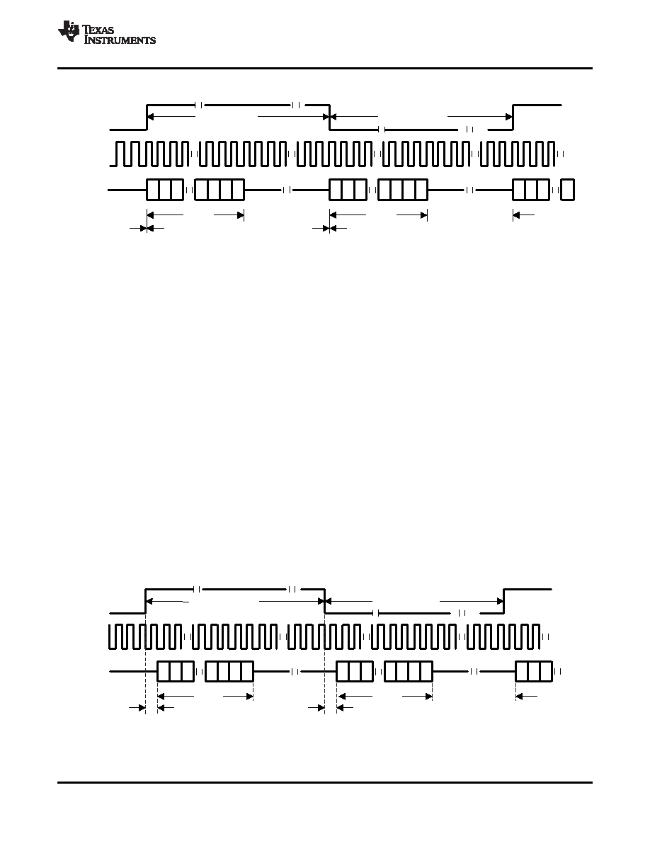
Figure 19 shows the left-justified mode with Ch_Offset_1 = 0 and bit clock inverted.
Figure 19. Left-Justified Mode With Ch_Offset_1 = 0, Bit Clock Inverted
For left-justified mode, the number of bit clocks per frame should be greater than twice the programmed word
length of the data. Also, the programmed offset value should be less than the number of bit clocks per frame by
at least the programmed word length of the data.
When the time-slot-based channel assignment is disabled (page 0 / register 38, bit D0 = 0), the left and right
channels have the same offset Ch_Offset_1 (page 0 / register 28), and each edge of the word clock starts data
transfer for one of the two channels, depending on whether or not channel swapping is enabled. Data bits are
valid on the rising edges of the bit clock. With the time-slot-based channel assignment enabled (page 0 / register
38, bit D0 = 1), the left and right channels have independent offsets (Ch_Offset_1 and Ch_Offset_2). The rising
edge of the word clock starts data transfer for the first channel after a delay of its programmed offset
(Ch_Offset_1) for this channel. Data transfer for the second channel starts after a delay of its programmed offset
(Ch_Offset_2) from the LSB of the first-channel data. The falling edge of the word clock is not used.
With no channel swapping, the MSB of the left channel is valid on the (Ch_Offset_1 + 1)th rising edge of the bit
clock following the rising edge of the word clock. And, the MSB of the right channel is valid on the (Ch_Offset_1
+ 1)th rising edge of the bit clock following the falling edge of the word clock. The operation in this case, with
offset of 1, is shown in the timing diagram of Figure 18. Because channel swapping is not enabled, the
left-channel data is before the right-channel data. With channel swapping enabled, the MSB of the right channel
is valid on the (Ch_Offset_1 + 1)th rising edge of the bit clock following the rising edge of the word clock. And,
the MSB of the left channel is valid on the (Ch_Offset_1 + 1)th rising edge of the bit clock following the falling
edge of the word clock. The operation in this case, with offset of 1, is shown in the timing diagram of Figure 20.
As shown in the diagram, right-channel data of a frame is before that frame’s left-channel data, due to channel
swapping. Otherwise, the behavior is similar to the case where channel swapping is disabled. The MSB of the
right-channel data is valid on the second rising edge of the bit clock after the rising edge of the word clock, due
to an offset of 1. Similarly, the MSB of the left-channel data is valid on the second rising edge of the bit clock
after the falling edge of the word clock.
Figure 20. Left-Justified Mode With Ch_Offset_1 = 1, Channel Swapping Enabled
Copyright 2008–2009, Texas Instruments Incorporated
19
Product Folder Link(s) :TLV320ADC3101
相關(guān)PDF資料 |
PDF描述 |
|---|---|
| TLV320ADC3101IRGET320 | SPECIALTY CONSUMER CIRCUIT, PQCC24 |
| TLV320ADC3101IRGER | SPECIALTY CONSUMER CIRCUIT, PQCC24 |
| TLV320ADC3101IRGET | SPECIALTY CONSUMER CIRCUIT, PQCC24 |
| TLV320AIC10C | SPECIALTY CONSUMER CIRCUIT, PQFP48 |
| TLV320AIC10I | SPECIALTY CONSUMER CIRCUIT, PQFP48 |
相關(guān)代理商/技術(shù)參數(shù) |
參數(shù)描述 |
|---|---|
| TLV320ADC3101IRGET | 功能描述:音頻模/數(shù)轉(zhuǎn)換器 IC 92dB (16B) Low Power Stereo ADC RoHS:否 制造商:Wolfson Microelectronics 轉(zhuǎn)換速率: 分辨率: ADC 輸入端數(shù)量: 工作電源電壓: 最大工作溫度: 最小工作溫度: 安裝風(fēng)格: 封裝 / 箱體: 封裝: |
| TLV320AIC10 | 制造商:TI 制造商全稱:Texas Instruments 功能描述:General-Purpose 3V to 5.5V 16-bit 22-KSPS DSP CODEC |
| TLV320AIC10C | 制造商:TI 制造商全稱:Texas Instruments 功能描述:General-Purpose 3V to 5.5V 16-bit 22-KSPS DSP CODEC |
| TLV320AIC10CGQER | 功能描述:接口—CODEC 16-Bit 22-KSPS DSP Codec RoHS:否 制造商:Texas Instruments 類型: 分辨率: 轉(zhuǎn)換速率:48 kSPs 接口類型:I2C ADC 數(shù)量:2 DAC 數(shù)量:4 工作電源電壓:1.8 V, 2.1 V, 2.3 V to 5.5 V 最大工作溫度:+ 85 C 安裝風(fēng)格:SMD/SMT 封裝 / 箱體:DSBGA-81 封裝:Reel |
| TLV320AIC10CPFB | 功能描述:接口—CODEC 16-Bit 22-KSPS DSP Codec RoHS:否 制造商:Texas Instruments 類型: 分辨率: 轉(zhuǎn)換速率:48 kSPs 接口類型:I2C ADC 數(shù)量:2 DAC 數(shù)量:4 工作電源電壓:1.8 V, 2.1 V, 2.3 V to 5.5 V 最大工作溫度:+ 85 C 安裝風(fēng)格:SMD/SMT 封裝 / 箱體:DSBGA-81 封裝:Reel |
發(fā)布緊急采購(gòu),3分鐘左右您將得到回復(fù)。