- 您現(xiàn)在的位置:買賣IC網(wǎng) > PDF目錄379454 > TLWY8900 (VISHAY SEMICONDUCTORS) LED Uni-Color Yellow 594nm 4-Pin Tube PDF資料下載
參數(shù)資料
| 型號: | TLWY8900 |
| 廠商: | VISHAY SEMICONDUCTORS |
| 元件分類: | 參考電壓二極管 |
| 英文描述: | LED Uni-Color Yellow 594nm 4-Pin Tube |
| 中文描述: | Standard LED - Through Hole Yellow Clr Non-Diff |
| 文件頁數(shù): | 1/9頁 |
| 文件大?。?/td> | 1298K |
| 代理商: | TLWY8900 |
TLWR8900, TLWR8901, TLWR8902, TLWR8903, TLWY8900
www.vishay.com
Vishay Semiconductors
Rev. 2.3, 23-Apr-13
1
Document Number: 83212
For technical questions, contact:
LED@vishay.com
THIS DOCUMENT IS SUBJECT TO CHANGE WITHOUT NOTICE. THE PRODUCTS DESCRIBED HEREIN AND THIS DOCUMENT
ARE SUBJECT TO SPECIFIC DISCLAIMERS, SET FORTH AT
www.vishay.com/doc91000
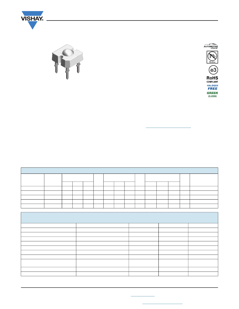
TELUX LED
DESCRIPTION
The TELUX series is a clear, non diffused LED for
applications where supreme luminous flux is required.
It is designed in an industry standard 7.62 mm square
package utilizing highly developed AllnGaP technology.
The supreme heat dissipation of TELUX allows applications
at high ambient temperatures.
All packing units are binned for luminous flux, forward
voltage, and color to achieve the most homogenous light
appearance in application.
SAE and ECE color requirements for automobile application
are available for color red.
PRODUCT GROUP AND PACKAGE DATA
Product group: LED
Package: TELUX
Product series: power
Angle of half intensity: ± 45°
FEATURES
High luminous flux
Supreme heat dissipation: R
thJP
is 90 K/W
High operating temperature:
T
amb
= - 40 °C to + 110 °C
Meets SAE and ECE color requirements for the
automobile industry for color red
Packed in tubes for automatic insertion
Luminous flux, forward voltage, and color
categorized for each tube
Small mechanical tolerances allow precise
usage of external reflectors or lightguides
Compatible with wave solder processes according to
CECC 00802
ESD-withstand voltage: Up to 2 kV according to
JESD22-A114-B
AEC-Q101 qualified
Material categorization: For definitions of compliance
please see
www.vishay.com/doc99912
APPLICATIONS
Exterior lighting
Dashboard illumination
Tail-, stop-, and turn signals of motor vehicles
Replaces small incandescent lamps
Traffic signals and signs
Note
(1)
Driving the LED in reverse direction is suitable for a short term application
19232
PARTS TABLE
PART
COLOR
LUMINOUS FLUX
(mlm)
MIN.
TYP.
2000
3000
2000
3000
3000
-
2500
-
2000
3000
at I
F
(mA)
WAVELENGTH
(nm)
MIN.
TYP.
611
615
611
615
611
615
611
615
585
590
at I
F
(mA)
FORWARD VOLTAGE
(V)
MIN.
TYP.
1.83
2.2
1.83
2.2
1.95
2.2
1.83
2.2
1.83
2.1
at I
F
(mA)
TECHNOLOGY
MAX.
-
4800
4800
4200
-
MAX.
634
634
634
634
597
MAX.
2.67
2.67
2.67
2.67
2.67
TLWR8900
TLWR8901
TLWR8902
TLWR8903
TLWY8900
Red
Red
Red
Red
Yellow
70
70
70
70
70
70
70
70
70
70
70
70
70
70
70
AlInGaP on GaAs
AlInGaP on GaAs
AlInGaP on GaAs
AlInGaP on GaAs
AlInGaP on GaAs
ABSOLUTE MAXIMUM RATINGS
(T
amb
= 25 °C, unless otherwise specified)
TLWR8900, TLWR8901, TLWR8902, TLWR8903, TLWY8900
PARAMETER
TEST CONDITION
Reverse voltage
(1)
DC forward current
Surge forward current
Power dissipation
Junction temperature
Operating temperature range
Storage temperature range
t
5 s, 1.5 mm from body preheat
temperature 100 °C/30 s
Thermal resistance junction/ambient
With cathode heatsink of 70 mm
2
Thermal resistance junction/pin
SYMBOL
V
R
I
F
I
FSM
P
V
T
j
T
amb
T
stg
VALUE
10
70
1
187
125
- 40 to + 110
- 55 to + 110
UNIT
V
mA
A
mW
°C
°C
°C
I
R
= 100 μA
T
amb
85 °C
t
p
10 μs
Soldering temperature
T
sd
260
°C
R
thJA
R
thJP
200
90
K/W
K/W
相關(guān)PDF資料 |
PDF描述 |
|---|---|
| TMPG06-7.5 | Automotive Transient Voltage Suppressor(汽車瞬變電壓抑制器) |
| TMPG06-6.8 | AUTOMOTIVE TRANSIENT VOLTAGE SUPPRESSOR |
| TMPG06-6.8A | AUTOMOTIVE TRANSIENT VOLTAGE SUPPRESSOR |
| TMPG06-8.2 | AUTOMOTIVE TRANSIENT VOLTAGE SUPPRESSOR |
| TMPG06-8.2A | AUTOMOTIVE TRANSIENT VOLTAGE SUPPRESSOR |
相關(guān)代理商/技術(shù)參數(shù) |
參數(shù)描述 |
|---|---|
| TLX032BJD-ASB | 功能描述:工業(yè)移動感應(yīng)器和位置傳感器 RESISTIVE & OPTICAL RoHS:否 制造商:Honeywell 輸出類型:Analog - Current 電壓額定值:12 VDC to 30 VDC 線性:+/- 0.0011 % 溫度范圍:- 40 C to + 85 C 總電阻: 容差: 類型:Rotary Sensor |
| TLX10B1P1E | 制造商:OMRON Industrial Automation 功能描述: 制造商:Omron Corporation 功能描述: |
| TL-X10B1-P1L | 制造商:Omron Corporation 功能描述: |
| TLX10B2P1E | 制造商:Omron Corporation 功能描述: |
| TLX10C1GE | 制造商:Omron Corporation 功能描述: |
發(fā)布緊急采購,3分鐘左右您將得到回復(fù)。