- 您現(xiàn)在的位置:買賣IC網(wǎng) > PDF目錄379454 > TLWY8900 (VISHAY SEMICONDUCTORS) LED Uni-Color Yellow 594nm 4-Pin Tube PDF資料下載
參數(shù)資料
| 型號: | TLWY8900 |
| 廠商: | VISHAY SEMICONDUCTORS |
| 元件分類: | 參考電壓二極管 |
| 英文描述: | LED Uni-Color Yellow 594nm 4-Pin Tube |
| 中文描述: | Standard LED - Through Hole Yellow Clr Non-Diff |
| 文件頁數(shù): | 2/9頁 |
| 文件大?。?/td> | 1298K |
| 代理商: | TLWY8900 |
TLWR8900, TLWR8901, TLWR8902, TLWR8903, TLWY8900
www.vishay.com
Vishay Semiconductors
Rev. 2.3, 23-Apr-13
2
Document Number: 83212
For technical questions, contact:
LED@vishay.com
THIS DOCUMENT IS SUBJECT TO CHANGE WITHOUT NOTICE. THE PRODUCTS DESCRIBED HEREIN AND THIS DOCUMENT
ARE SUBJECT TO SPECIFIC DISCLAIMERS, SET FORTH AT
www.vishay.com/doc91000
Note
Luminous flux is tested at a current pulse duration of 25 ms and
an accuracy of ± 11 %.
These type numbers represent the order groups which include
only a few brightness groups. Only one group will be shipped on
each tube (there will be no mixing of two groups on each tube).
In order to ensure availability, single brightness groups will not
be orderable.
In a similar manner for colors where wavelength groups are
measured and binned, single wavelength groups will be shipped
in any one tube.
In order to ensure availability, single wavelength groups will not
be orderable.
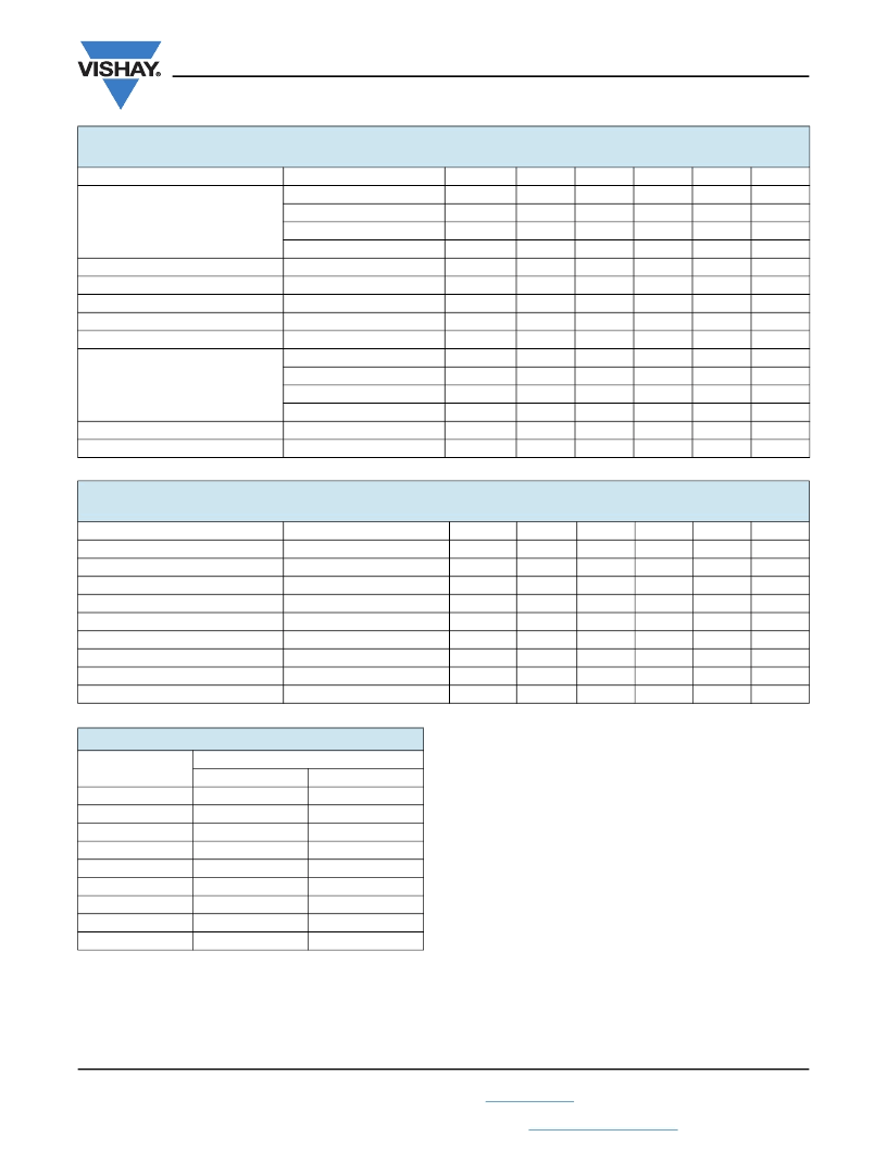
OPTICAL AND ELECTRICAL CHARACTERISTICS
(T
amb
= 25 °C, unless otherwise specified)
TLWR8900, TLWR8901, TLWR8902, TLWR8903, RED
PARAMETER
TEST CONDITION
I
F
= 70 mA, R
thJA
= 200 K/W
I
F
= 70 mA, R
thJA
= 200 K/W
I
F
= 70 mA, R
thJA
= 200 K/W
I
F
= 70 mA, R
thJA
= 200 K/W
Luminous intensity/total flux
Dominant wavelength
Peak wavelength
Angle of half intensity
Total included angle
90 % of total flux captured
I
F
= 70 mA, R
thJA
= 200 K/W
I
F
= 70 mA, R
thJA
= 200 K/W
I
F
= 70 mA, R
thJA
= 200 K/W
I
F
= 70 mA, R
thJA
= 200 K/W
Reverse voltage
I
R
= 10 μA
Junction capacitance
V
R
= 0 V, f = 1 MHz
PART
TLWR8900
TLWR8901
TLWR8902
TLWR8903
SYMBOL
V
V
V
V
I
V
/
V
d
p
0.9 V
V
F
V
F
V
F
V
F
V
R
C
j
MIN.
2000
2000
3000
2500
-
611
-
-
-
1.83
1.83
1.95
1.83
10
-
TYP.
3000
3000
-
-
0.7
615
624
± 45
100
2.2
2.2
2.2
2.2
20
17
MAX.
-
4800
4800
4200
-
634
-
-
-
2.67
2.67
2.67
2.67
-
-
UNIT
mlm
mlm
mlm
mlm
mcd/mlm
nm
nm
deg
deg
V
V
V
V
V
pF
Total flux
Forward voltage
TLWR8900
TLWR8901
TLWR8902
TLWR8903
OPTICAL AND ELECTRICAL CHARACTERISTICS
(T
amb
= 25 °C, unless otherwise specified)
TLWY8900, YELLOW
PARAMETER
TEST CONDITION
Total flux
I
F
= 70 mA, R
thJA
= 200 K/W
Luminous intensity/total flux
I
F
= 70 mA, R
thJA
= 200 K/W
Dominant wavelength
I
F
= 70 mA, R
thJA
= 200 K/W
Peak wavelength
I
F
= 70 mA, R
thJA
= 200 K/W
Angle of half intensity
I
F
= 70 mA, R
thJA
= 200 K/W
Total included angle
90 % of total flux captured
Forward voltage
I
F
= 70 mA, R
thJA
= 200 K/W
Reverse voltage
I
R
= 10 μA
Junction capacitance
V
R
= 0 V, f = 1 MHz
PART
SYMBOL
V
I
V
/
V
d
p
0.9 V
V
F
V
R
C
j
MIN.
2000
-
585
-
-
-
1.83
10
-
TYP.
3000
0.7
590
594
± 45
100
2.1
15
17
MAX.
-
-
597
-
-
-
2.67
-
-
UNIT
mlm
mcd/mlm
nm
nm
deg
deg
V
V
pF
LUMINOUS FLUX CLASSIFICATION
GROUP
LUMINOUS FLUX (mlm)
MIN.
2000
2500
3000
3500
4000
5000
6000
7000
8000
MAX.
3000
3600
4200
4800
6100
7300
9700
12 200
15 000
D
E
F
G
H
I
K
L
M
相關(guān)PDF資料 |
PDF描述 |
|---|---|
| TMPG06-7.5 | Automotive Transient Voltage Suppressor(汽車瞬變電壓抑制器) |
| TMPG06-6.8 | AUTOMOTIVE TRANSIENT VOLTAGE SUPPRESSOR |
| TMPG06-6.8A | AUTOMOTIVE TRANSIENT VOLTAGE SUPPRESSOR |
| TMPG06-8.2 | AUTOMOTIVE TRANSIENT VOLTAGE SUPPRESSOR |
| TMPG06-8.2A | AUTOMOTIVE TRANSIENT VOLTAGE SUPPRESSOR |
相關(guān)代理商/技術(shù)參數(shù) |
參數(shù)描述 |
|---|---|
| TLX032BJD-ASB | 功能描述:工業(yè)移動感應器和位置傳感器 RESISTIVE & OPTICAL RoHS:否 制造商:Honeywell 輸出類型:Analog - Current 電壓額定值:12 VDC to 30 VDC 線性:+/- 0.0011 % 溫度范圍:- 40 C to + 85 C 總電阻: 容差: 類型:Rotary Sensor |
| TLX10B1P1E | 制造商:OMRON Industrial Automation 功能描述: 制造商:Omron Corporation 功能描述: |
| TL-X10B1-P1L | 制造商:Omron Corporation 功能描述: |
| TLX10B2P1E | 制造商:Omron Corporation 功能描述: |
| TLX10C1GE | 制造商:Omron Corporation 功能描述: |
發(fā)布緊急采購,3分鐘左右您將得到回復。