- 您現(xiàn)在的位置:買賣IC網(wǎng) > PDF目錄368671 > TMS320C242PGS 16-Bit Digital Signal Processor PDF資料下載
參數(shù)資料
| 型號: | TMS320C242PGS |
| 元件分類: | 數(shù)字信號處理 |
| 英文描述: | 16-Bit Digital Signal Processor |
| 中文描述: | 16位數(shù)字信號處理器 |
| 文件頁數(shù): | 28/66頁 |
| 文件大?。?/td> | 803K |
| 代理商: | TMS320C242PGS |
第1頁第2頁第3頁第4頁第5頁第6頁第7頁第8頁第9頁第10頁第11頁第12頁第13頁第14頁第15頁第16頁第17頁第18頁第19頁第20頁第21頁第22頁第23頁第24頁第25頁第26頁第27頁當(dāng)前第28頁第29頁第30頁第31頁第32頁第33頁第34頁第35頁第36頁第37頁第38頁第39頁第40頁第41頁第42頁第43頁第44頁第45頁第46頁第47頁第48頁第49頁第50頁第51頁第52頁第53頁第54頁第55頁第56頁第57頁第58頁第59頁第60頁第61頁第62頁第63頁第64頁第65頁第66頁

TMS320C242
DSP CONTROLLER
SPRS063B – DECEMBER 1997 – REVISED DECEMBER 1999
28
POST OFFICE BOX 1443
HOUSTON, TEXAS 77251–1443
’24x legend for the internal hardware functional block diagram (continued)
Table 8. Legend for the ’24x Internal Hardware Functional Block Diagram (Continued)
SYMBOL
NAME
DESCRIPTION
PREG
Product Register
32-bit register holds results of 16
×
16 multiply
0-, 1-, or 4-bit left shift, or 6-bit right shift of multiplier product. The left-shift options are used to manage the
additional sign bits resulting from the 2s-complement multiply. The right-shift option is used to scale down
the number to manage overflow of product accumulation in the CALU. PSCALE resides in the path from the
32-bit product shifter and from either the CALU or the data-write data bus (DWEB), and requires no cycle
overhead.
PSCALE
Product-Scaling
Shifter
STACK
Stack
STACK is a block of memory used for storing return addresses for subroutines and interrupt-service
routines, or for storing data. The ’C24x stack is 16-bit wide and eight-level deep.
TREG
Temporary
Register
16-bit register holds one of the operands for the multiply operations. TREG holds the dynamic shift count
for the LACT, ADDT, and SUBT instructions. TREG holds the dynamic bit position for the BITT instruction.
’C242 DSP core CPU
The TMS320x24x devices use an advanced Harvard-type architecture that maximizes processing power by
maintaining two separate memory bus structures — program and data — for full-speed execution. This multiple
bus structure allows data and instructions to be read simultaneously. Instructions support data transfers
between program memory and data memory. This architecture permits coefficients that are stored in program
memory to be read in RAM, thereby eliminating the need for a separate coefficient ROM. This, coupled with a
four-deep pipeline, allows the ’C242 to execute most instructions in a single cycle.
Please refer to the TMS320F243/F241 datasheet (SPRS064), specifically the ’F243/241 DSP core CPU
section; the TMS320C24x CPU System and Instruction Set, Volume 1(SPRU160); and the
TMS320F243,F241,C242 DSP Controllers System and Peripherals User’s Guide Volume 2 literature number
SPRU276) for more information regarding the CPU, input scaling shifter, multiplier, central arithmetic logic unit,
accumulator, auxiliary registers, and the auxiliary-register arithmetic unit.
status and control registers
Two status registers, ST0 and ST1, contain the status of various conditions and modes. These registers can
be stored into data memory and loaded from data memory, thus allowing the status of the machine to be saved
and restored for subroutines.
The load status register (LST) instruction is used to write to ST0 and ST1. The store status register (SST)
instruction is used to read from ST0 and ST1 — except for the INTM bit, which is not affected by the LST
instruction. The individual bits of these registers can be set or cleared when using the SETC and CLRC
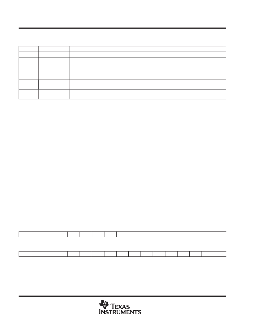
instructions. Figure 8 shows the organization of status registers ST0 and ST1, indicating all status bits contained
in each. Several bits in the status registers are reserved and are read as logic 1s. Table 9 lists status register
field definitions.
15
13
12
11
10
9
8
0
ST0
ARP
OV
OVM
1
INTM
DP
15
13
12
11
10
9
8
7
6
5
4
3
2
1
0
ST1
ARB
CNF
TC
SXM
C
1
1
1
1
XF
1
1
PM
Figure 8. Status and Control Register Organization
A
相關(guān)PDF資料 |
PDF描述 |
|---|---|
| TMS320C30GEL | 32-Bit Digital Signal Processor |
| SM320C25FJM | 16-Bit Digital Signal Processor |
| SM320C25GBM | 16-Bit Digital Signal Processor |
| SM320C40TABC50 | 32-Bit Digital Signal Processor |
| SM320C40TABM40 | 32-Bit Digital Signal Processor |
相關(guān)代理商/技術(shù)參數(shù) |
參數(shù)描述 |
|---|---|
| TMS320C25 | 制造商:TI 制造商全稱:Texas Instruments 功能描述:SECOND-GENERATION DIGITAL SIGNAL PROCESSORS |
| TMS320C25/-33/-50 | 制造商:未知廠家 制造商全稱:未知廠家 功能描述:16-Bit Digital Signal Processor |
| TMS320C25-50 | 制造商:TI 制造商全稱:Texas Instruments 功能描述:SECOND-GENERATION DIGITAL SIGNAL PROCESSORS |
| TMS320C25FNA | 功能描述:數(shù)字信號處理器和控制器 - DSP, DSC Digital Signal Proc RoHS:否 制造商:Microchip Technology 核心:dsPIC 數(shù)據(jù)總線寬度:16 bit 程序存儲器大小:16 KB 數(shù)據(jù) RAM 大小:2 KB 最大時鐘頻率:40 MHz 可編程輸入/輸出端數(shù)量:35 定時器數(shù)量:3 設(shè)備每秒兆指令數(shù):50 MIPs 工作電源電壓:3.3 V 最大工作溫度:+ 85 C 封裝 / 箱體:TQFP-44 安裝風(fēng)格:SMD/SMT |
| TMS320C25FNA50 | 功能描述:數(shù)字信號處理器和控制器 - DSP, DSC DIGITAL SIGNAL PROCESSORS RoHS:否 制造商:Microchip Technology 核心:dsPIC 數(shù)據(jù)總線寬度:16 bit 程序存儲器大小:16 KB 數(shù)據(jù) RAM 大小:2 KB 最大時鐘頻率:40 MHz 可編程輸入/輸出端數(shù)量:35 定時器數(shù)量:3 設(shè)備每秒兆指令數(shù):50 MIPs 工作電源電壓:3.3 V 最大工作溫度:+ 85 C 封裝 / 箱體:TQFP-44 安裝風(fēng)格:SMD/SMT |
發(fā)布緊急采購,3分鐘左右您將得到回復(fù)。