- 您現(xiàn)在的位置:買賣IC網(wǎng) > PDF目錄359304 > TMS320M642AGDK6 (Texas Instruments, Inc.) 1A, 52kHz (250kHz Max) Current Mode PWM Control Circuit with 8.4V UVLO Threshold and 96% Max Duty Cycle; Package: SOIC 14 LEAD; No of Pins: 14; Container: Tape and Reel; Qty per Container: 2500 PDF資料下載
參數(shù)資料
| 型號: | TMS320M642AGDK6 |
| 廠商: | Texas Instruments, Inc. |
| 英文描述: | 1A, 52kHz (250kHz Max) Current Mode PWM Control Circuit with 8.4V UVLO Threshold and 96% Max Duty Cycle; Package: SOIC 14 LEAD; No of Pins: 14; Container: Tape and Reel; Qty per Container: 2500 |
| 中文描述: | 視頻/影像定點(diǎn)數(shù)字信號處理器 |
| 文件頁數(shù): | 92/123頁 |
| 文件大小: | 1205K |
| 代理商: | TMS320M642AGDK6 |
第1頁第2頁第3頁第4頁第5頁第6頁第7頁第8頁第9頁第10頁第11頁第12頁第13頁第14頁第15頁第16頁第17頁第18頁第19頁第20頁第21頁第22頁第23頁第24頁第25頁第26頁第27頁第28頁第29頁第30頁第31頁第32頁第33頁第34頁第35頁第36頁第37頁第38頁第39頁第40頁第41頁第42頁第43頁第44頁第45頁第46頁第47頁第48頁第49頁第50頁第51頁第52頁第53頁第54頁第55頁第56頁第57頁第58頁第59頁第60頁第61頁第62頁第63頁第64頁第65頁第66頁第67頁第68頁第69頁第70頁第71頁第72頁第73頁第74頁第75頁第76頁第77頁第78頁第79頁第80頁第81頁第82頁第83頁第84頁第85頁第86頁第87頁第88頁第89頁第90頁第91頁當(dāng)前第92頁第93頁第94頁第95頁第96頁第97頁第98頁第99頁第100頁第101頁第102頁第103頁第104頁第105頁第106頁第107頁第108頁第109頁第110頁第111頁第112頁第113頁第114頁第115頁第116頁第117頁第118頁第119頁第120頁第121頁第122頁第123頁

www.ti.com
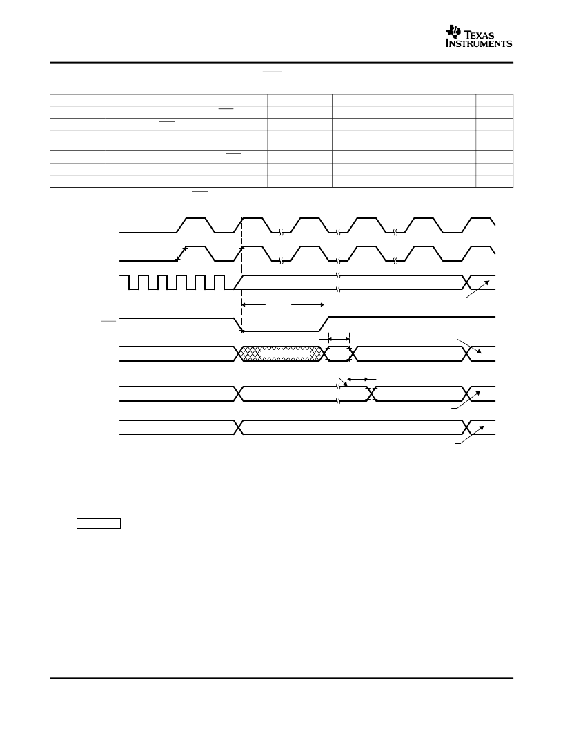
t
h(boot-mode)(A)
t
w(RSL2)
XCLKIN
X1/X2
XRS
Boot-Mode
Pins
XCLKOUT
I/O Pins
Address/Data/
Control
(Internal)
Boot-ROM Execution Starts
User-Code Execution Starts
User-Code Dependent
User-Code Execution Phase
(Don’t Care)
User-Code Dependent
User-Code Execution
Peripheral/GPIO Function
User-Code Dependent
GPIO Pins as Input (State Depends on Internal PU/PD)
GPIO Pins as Input
Peripheral/GPIO Function
t
d(EX)
OSCCLK * 5
OSCCLK/8
TMS320F2808, TMS320F2806
TMS320F2801, UCD9501
Digital Signal Processors
SPRS230F–OCTOBER 2003–REVISED SEPTEMBER 2005
Table 6-11. Reset (XRS) Timing Requirements
MIN
NOM
MAX
UNIT
cycles
cycles
t
w(RSL1)(1)
t
w(RSL2)
Pulse duration, stable XCLKIN to XRS high
Pulse duration, XRS low
Pulse duration, reset pulse generated by
watchdog
Delay time, address/data valid after XRS high
Oscillator start-up time
Hold time for boot-mode pins
8t
c(OSCCLK)
8t
c(OSCCLK)
Warm reset
t
w(WDRS)
512t
c(OSCCLK)
cycles
t
d(EX)
t
OSCST(2)
t
h(boot-mode)
(1)
In addition to the t
requirement, XRS has to be low at least for 1 ms after V
DD
reaches 1.5 V.
(2)
Dependent on crystal/resonator and board design.
32t
c(OSCCLK)
cycles
ms
cycles
1
10
200t
c(OSCCLK)
A.
After reset, the Boot ROM code samples BOOT Mode pins. Based on the status of the Boot Mode pin, the boot code
branches to destination memory or boot code function. If Boot ROM code executes after power-on conditions (in
debugger environment), the Boot code execution time is based on the current SYSCLKOUT speed. The
SYSCLKOUT will be based on user environment and could be with or without PLL enabled.
Figure 6-6. Warm Reset
Figure 6-7
shows an example for the effect of writing into PLLCR register. In the first phase, PLLCR =
0x0004 and SYSCLKOUT = OSCCLK x 2. The PLLCR is then written with 0x0008. Right after the PLLCR
register is written, the PLL lock-up phase begins. During this phase, SYSCLKOUT = OSCCLK/2. After the
PLL lock-up is complete (which takes 131072 OSCCLK cycles), SYSCLKOUT reflects the new operating
frequency, OSCCLK x 4.
92
Electrical Specifications
相關(guān)PDF資料 |
PDF描述 |
|---|---|
| TMS320M642AGDK7 | Video/Imaging Fixed-Point Digital Signal Processor |
| TMS320E17 | 200mA, 40kHz PWM Control Circuit with 6.4V UVLO Threshold and 48% Max Duty Cycle; Package: SOIC 16 LEAD; No of Pins: 16; Container: Tape and Reel; Qty per Container: 2500 |
| TMS320LC2402 | 32A 24-32V Transient Suppressor ; Package: Can Button; No of Pins: 2; Container: Bulk; Qty per Container: 5000 |
| TMS320LC2402PZ | Zero Voltage Switch Power Controller for Triacs; Package: 8 LEAD PDIP; No of Pins: 8; Container: Rail; Qty per Container: 50 |
| TMS320M642AZDK6 | 1A, 52kHz (250kHz Max) Current Mode PWM Control Circuit with 16V UVLO Threshold and 48% Max Duty Cycle; Package: SOIC-8 Narrow Body; No of Pins: 8; Container: Tape and Reel; Qty per Container: 2500 |
相關(guān)代理商/技術(shù)參數(shù) |
參數(shù)描述 |
|---|---|
| TMS320M642AGDK7 | 制造商:Texas Instruments 功能描述:DSP FIX PT 32BIT 720MHZ 5760MIPS 548FCBGA - Trays |
| TMS320M642AGNZ5 | 制造商:Texas Instruments 功能描述:TMS320DM642A PG2 548PIN FCBGA 500 MHZ - Trays |
| TMS320M642AGNZ6 | 制造商:Texas Instruments 功能描述:TMS320DM642A PG2 548PIN FCBGA 600 MHZ - Trays |
| TMS320M642AGNZ6ADB | 制造商:Texas Instruments 功能描述: |
| TMS320M642AGNZ7 | 制造商:Texas Instruments 功能描述:DSP FIX PT 32BIT 720MHZ 5760MIPS 548FCBGA - Trays |
發(fā)布緊急采購,3分鐘左右您將得到回復(fù)。