- 您現(xiàn)在的位置:買賣IC網(wǎng) > PDF目錄98272 > TPA3004D2PHPG4 (TEXAS INSTRUMENTS INC) 2 CHANNEL(S), VOLUME CONTROL CIRCUIT, PQFP48 PDF資料下載
參數(shù)資料
| 型號(hào): | TPA3004D2PHPG4 |
| 廠商: | TEXAS INSTRUMENTS INC |
| 元件分類: | 音頻控制 |
| 英文描述: | 2 CHANNEL(S), VOLUME CONTROL CIRCUIT, PQFP48 |
| 封裝: | GREEN, PLASTIC, HTQFP-48 |
| 文件頁數(shù): | 19/46頁 |
| 文件大小: | 838K |
| 代理商: | TPA3004D2PHPG4 |
第1頁第2頁第3頁第4頁第5頁第6頁第7頁第8頁第9頁第10頁第11頁第12頁第13頁第14頁第15頁第16頁第17頁第18頁當(dāng)前第19頁第20頁第21頁第22頁第23頁第24頁第25頁第26頁第27頁第28頁第29頁第30頁第31頁第32頁第33頁第34頁第35頁第36頁第37頁第38頁第39頁第40頁第41頁第42頁第43頁第44頁第45頁第46頁
VARMAX (V)
VOLUME–VARDIFF
VARDIFF (V)
–
+
VOLUME (V)
NO
YES
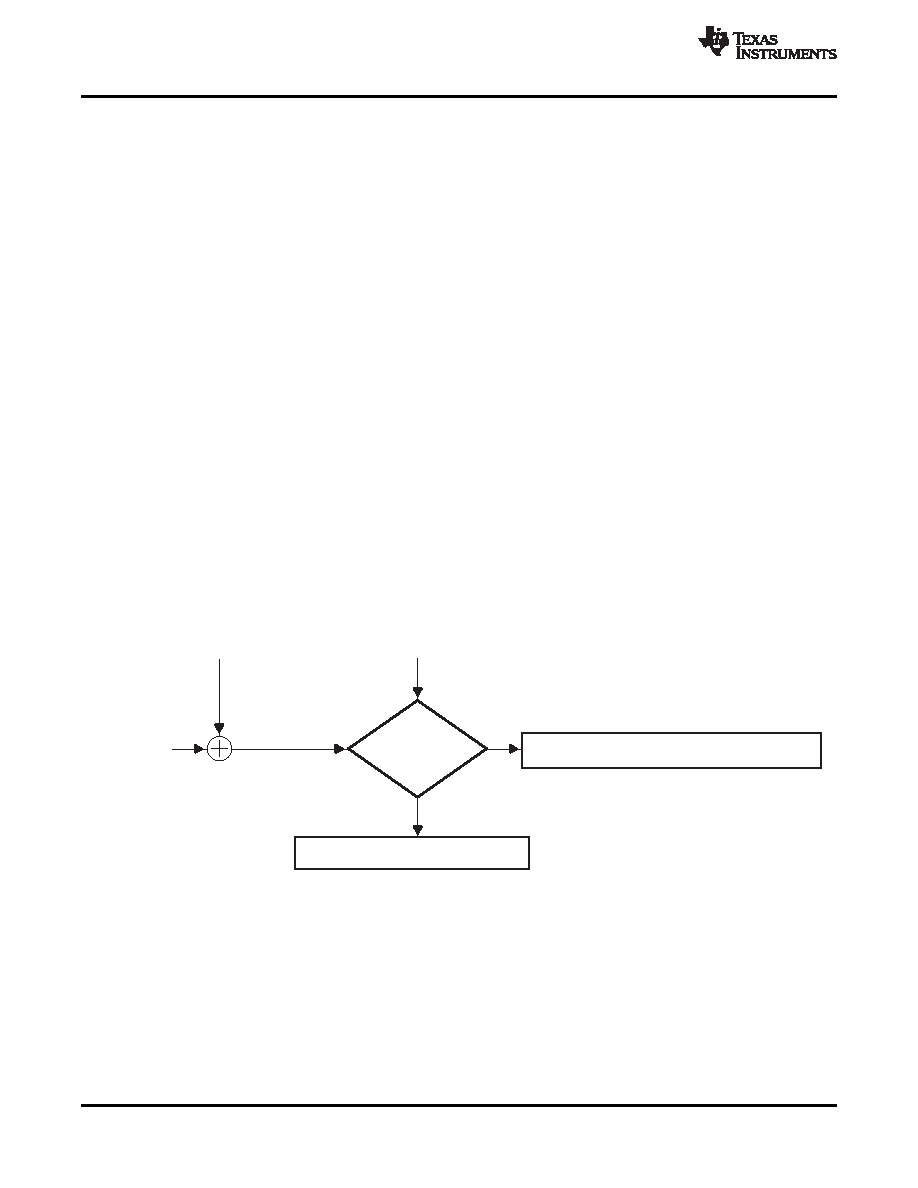
VAROUT_VOLUME (V) = VOLUME (V) – VARDIFF (V)
VAROUT_VOLUME (V) = VARMAX (V)
Is VARMAX>
(VOLUME–VARDIFF)
?
SLOS407E – FEBRUARY 2003 – REVISED JANUARY 2011
www.ti.com
The trip point, where the gain actually changes, is different depending on whether the voltage on the VOLUME
terminal is increasing or decreasing as a result of hysteresis about each trip point. The hysteresis ensures that
the gain control is monotonic and does not oscillate from one gain step to another. A pictorial representation of
the volume control can be found in Figure 43. The graph focuses on three gain steps with the trip points defined
in the first and second columns of Table 1 for class-D gain. The dotted lines represent the hysteresis about each
gain step.
The timing of the volume control circuitry is controlled by an internal 60 Hz clock. This clock determines the rate
at which the gain changes when adjusting the voltage on the external volume control pins. The gain updates
every 4 clock cycles (nominally 67 ms based on a 60 Hz clock) to the next step until the final desired gain is
reached. For example, if the TPA3004D2 is currently in the +0.53 db class-D gain step and the VOLUME pin is
adjusted for maximum gain at +36 dB, the time required for the gain to reach 36dB is 14 steps x 67ms/step =
0.938 seconds. Referencing Table 1, there are 14 steps between the +0.53 dB gain step and the maximum gain
step of +36 dB.
VARDIFF and VARMAX Operation
The TPA3004D2 allows the user to specify a difference between the class-D gain and VAROUT gain. This is
desirable to avoid any listening discomfort when plugging in headphones. When interfacing with the variable
outputs, the VARDIFF and VARMAX pins control the VAROUT channel gain proportional to the gain set by the
voltage on the VOLUME pin. When VARDIFF=0 V, the difference between the class-D gain and the VAROUT
gain is 16 dB. As the voltage on the VARDIFF terminal is increased, the VAROUT channel gain decreases.
Internal to the TPA3004D2 device, the voltage on the VARDIFF terminal is subtracted from the voltage on the
VOLUME terminal and this value is used to determine the VAROUT gain.
Some audio systems require that the gain be limited in the VAROUT mode to a level that is comfortable for
headphone listening. The VARMAX terminal controls the maximum gain for the VAROUT channels.
The functionality of the VARDIFF and VARMAX pin are combined to fix the VAROUT channel gain. A block
diagram of the combined functionality is shown in Figure 42. The value obtained from the block diagram for
VAROUT_VOLUME is a DC voltage that can be used in conjunction with Table 2 to determine the VAROUT
channel gain. Table 2 lists the gain in VAROUT mode as determined by the VAROUT_VOLUME voltage in
reference to the voltage on VREF.
Figure 42. Block Diagram of VAROUT Volume Control
26
Copyright 2003–2011, Texas Instruments Incorporated
Product Folder Link(s): TPA3004D2
相關(guān)PDF資料 |
PDF描述 |
|---|---|
| TPA3005D2PHPR | 6 W, 2 CHANNEL, AUDIO AMPLIFIER, PQFP48 |
| TPA3005D2PHP | 6 W, 2 CHANNEL, AUDIO AMPLIFIER, PQFP48 |
| TPA3005D2PHPG4 | 6 W, 2 CHANNEL, AUDIO AMPLIFIER, PQFP48 |
| TPA3005D2PHPRG4 | 6 W, 2 CHANNEL, AUDIO AMPLIFIER, PQFP48 |
| TPA3007D1PWR | 6.5 W, 1 CHANNEL, AUDIO AMPLIFIER, PDSO24 |
相關(guān)代理商/技術(shù)參數(shù) |
參數(shù)描述 |
|---|---|
| TPA3004D2PHPR | 功能描述:音頻放大器 Stereo Hi-Pwr Filter-Free Class-D RoHS:否 制造商:STMicroelectronics 產(chǎn)品:General Purpose Audio Amplifiers 輸出類型:Digital 輸出功率: THD + 噪聲: 工作電源電壓:3.3 V 電源電流: 最大功率耗散: 最大工作溫度: 安裝風(fēng)格:SMD/SMT 封裝 / 箱體:TQFP-64 封裝:Reel |
| TPA3004D2PHPR | 制造商:Texas Instruments 功能描述:AUDIO POWER AMPLIFIER IC |
| TPA3004D2PHPRG4 | 功能描述:音頻放大器 Stereo Hi-Pwr Filter-Free Class-D RoHS:否 制造商:STMicroelectronics 產(chǎn)品:General Purpose Audio Amplifiers 輸出類型:Digital 輸出功率: THD + 噪聲: 工作電源電壓:3.3 V 電源電流: 最大功率耗散: 最大工作溫度: 安裝風(fēng)格:SMD/SMT 封裝 / 箱體:TQFP-64 封裝:Reel |
| TPA3005D2 | 制造商:TI 制造商全稱:Texas Instruments 功能描述:6-W STEREO CLASS-D AUDIO POWER AMPLIFIER |
| TPA3005D2EVM | 功能描述:音頻 IC 開發(fā)工具 TPA3005D2 Eval Mod RoHS:否 制造商:Texas Instruments 產(chǎn)品:Evaluation Kits 類型:Audio Amplifiers 工具用于評(píng)估:TAS5614L 工作電源電壓:12 V to 38 V |
發(fā)布緊急采購,3分鐘左右您將得到回復(fù)。