- 您現(xiàn)在的位置:買賣IC網(wǎng) > PDF目錄98281 > TPS40131RHBT (TEXAS INSTRUMENTS INC) SWITCHING CONTROLLER, 1200 kHz SWITCHING FREQ-MAX, PQCC32 PDF資料下載
參數(shù)資料
| 型號(hào): | TPS40131RHBT |
| 廠商: | TEXAS INSTRUMENTS INC |
| 元件分類: | 穩(wěn)壓器 |
| 英文描述: | SWITCHING CONTROLLER, 1200 kHz SWITCHING FREQ-MAX, PQCC32 |
| 封裝: | GREEN, PLASTIC, QFN-32 |
| 文件頁數(shù): | 4/40頁 |
| 文件大?。?/td> | 940K |
| 代理商: | TPS40131RHBT |
第1頁第2頁第3頁當(dāng)前第4頁第5頁第6頁第7頁第8頁第9頁第10頁第11頁第12頁第13頁第14頁第15頁第16頁第17頁第18頁第19頁第20頁第21頁第22頁第23頁第24頁第25頁第26頁第27頁第28頁第29頁第30頁第31頁第32頁第33頁第34頁第35頁第36頁第37頁第38頁第39頁第40頁
www.ti.com
Overvoltage Protection, Non-Latching
Output Undervoltage Protection
Programmable Input Undervoltage Lockout Protection
Power-On Reset (POR)
Fault Masking Operation
Fault Conditions and MOSFET Control
SLVS635 – FEBRUARY 2007
FUNCTIONAL DESCRIPTION (continued)
If the overcurrent condition persists, both phases have PWM cycles terminated by the overcurrent signals. This
puts a converter in a constant current mode with the output current programmed by the ILIM voltage. A counter
is incremented for each PWM cycle in which an overcurrent event is detected. The counter is reset every 32
PWM cycles. If the counter accumulates a count of 7 before being reset, the converter enters a hiccup mode.
The HDRV and LDRV signals are set low during the hiccup mode.
The SS capacitor serves as a hiccup timing capacitor controlled by U20, the fault control circuit. The soft-start
pin is periodically charged and discharged by U20. After seven hiccup cycles, the controller attempts another
soft-start cycle to restore normal operation. If the overload condition persists, the controller returns to the hiccup
mode. This condition may continue indefinitely. In such conditions the average current delivered to the load is
approximately 1/8 of the set overcurrent value.
The voltage on OVSET is compared with 0.817 V, 16% higher than VREF, in U25 to determine the output
overvoltage point. When an overvoltage is detected, the output drivers command the upper MOSFETs off and
the lower MOSFETs on. If the overvoltage condition has been cleared, the output comes up and normal
operation continues. Turning the lower MOSFET on may cause the output to reach an undervoltage condition
and enter the hiccup mode. Using a voltage divider with the same ratio, that sets the output voltage, an output
overvoltage is declared when the output rises 16% above nominal.
If the output voltage, as sensed by U19 on the FB pin becomes less than 0.588 V, the undervoltage protection
threshold (84% of VREF), the controller enters the hiccup mode.
A voltage divider that sets 1V on the UVLO pin determines when the controller starts operating. Operation
commences when the voltage on the UVLO pin exceeds 1.0 V. If the voltage on the UVLO pin falls to 0.81 V,
the controller is turned off and the HDRV and LDRV signals are set low.
The power-on reset (POR) function, U22, insures the VIN5 and BP5 voltages are within their regulation windows
before the controller is allowed to start.
If the SS pin voltage is externally limited below the 1-V threshold, the controller does not respond to most faults
and the PGOOD output is always low. Only the overcurrent function remains active. The overcurrent protection
still continues to terminate PWM cycle every time when the threshold is exceeded but the hiccup mode is not
entered.
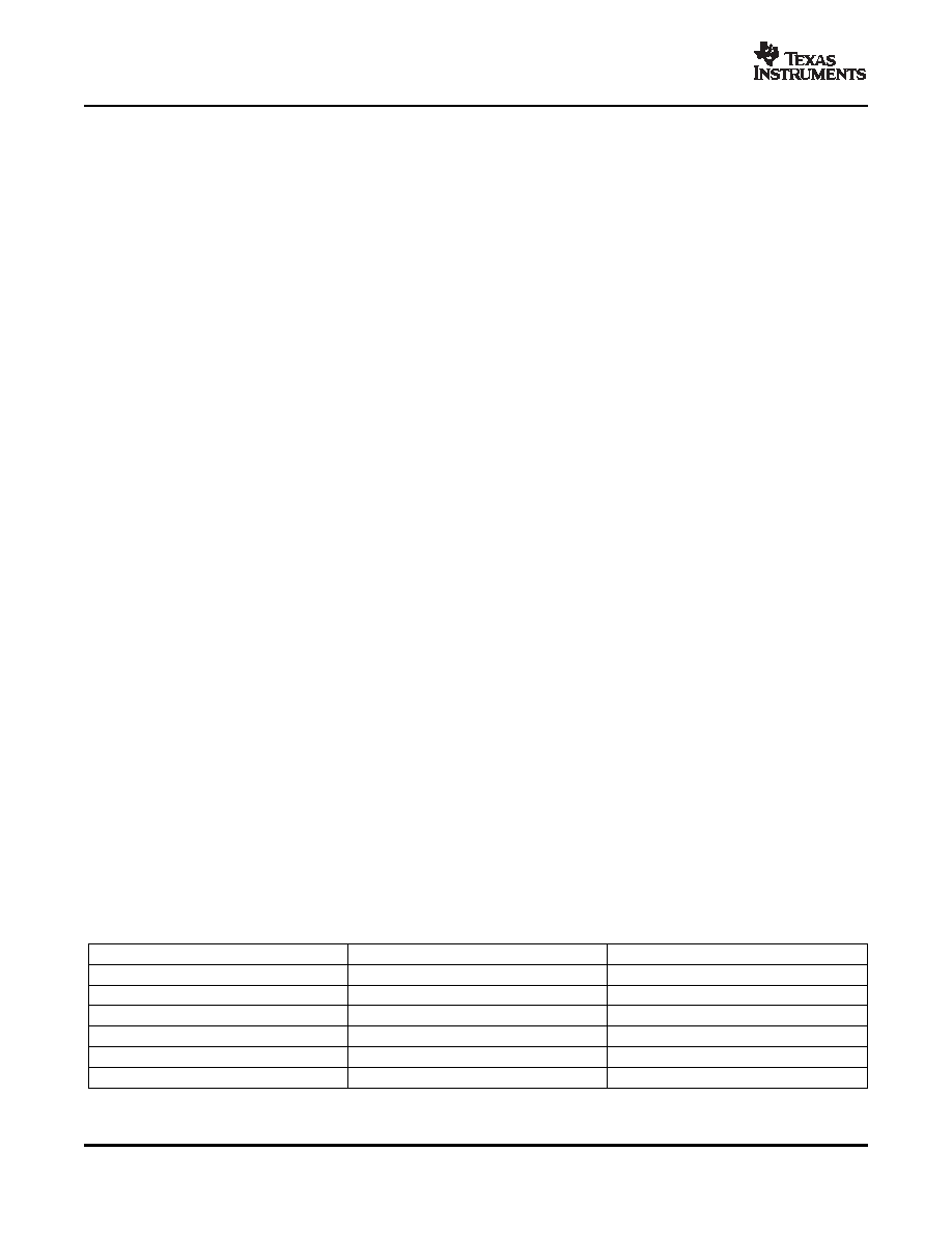
Table 1 shows a summary of the fault conditions and the state of the MOSFETs.
Table 1. Fault Condifions
FAULT MODE
UPPER MOSFET
LOWER MOSFET
EN/SYNC = LOW
OFF
FIXED UVLO, VBP5 < 4.25 V
OFF
Programmable UVLO, < 1.0 V
OFF
Output undervoltage
OFF, Hiccup mode
Output overvoltage
OFF
ON
Output overcurrent
OFF, Hiccup mode
12
相關(guān)PDF資料 |
PDF描述 |
|---|---|
| TPS40131RHBTG4 | SWITCHING CONTROLLER, 1200 kHz SWITCHING FREQ-MAX, PQCC32 |
| TPS40131RHBR | SWITCHING CONTROLLER, 1200 kHz SWITCHING FREQ-MAX, PQCC32 |
| TPS40132RHBR | 40 A SWITCHING CONTROLLER, 1200 kHz SWITCHING FREQ-MAX, PQCC32 |
| TPS40197RGYR | SWITCHING CONTROLLER, 520 kHz SWITCHING FREQ-MAX, PQCC16 |
| TPS40200MDREPG4 | SWITCHING CONTROLLER, 500 kHz SWITCHING FREQ-MAX, PDSO8 |
相關(guān)代理商/技術(shù)參數(shù) |
參數(shù)描述 |
|---|---|
| TPS40131RHBT | 制造商:Texas Instruments 功能描述:DC/DC Converter (DC-DC) / Switching Regu 制造商:Texas Instruments 功能描述:IC, SYNC BUCK CONTROLLER, QFN-32 |
| TPS40131RHBTG4 | 功能描述:DC/DC 開關(guān)控制器 Two-Phase Synch Buck Cntrlr RoHS:否 制造商:Texas Instruments 輸入電壓:6 V to 100 V 開關(guān)頻率: 輸出電壓:1.215 V to 80 V 輸出電流:3.5 A 輸出端數(shù)量:1 最大工作溫度:+ 125 C 安裝風(fēng)格: 封裝 / 箱體:CPAK |
| TPS40132 | 制造商:TI 制造商全稱:Texas Instruments 功能描述:TWO-PHASE, SYNCHRONOUS BUCK CONTROLLER WITH INTEGRATED MOSFET DRIVERS |
| TPS40132RHBR | 功能描述:DC/DC 開關(guān)控制器 2Ch Multiphase Cntrlr RoHS:否 制造商:Texas Instruments 輸入電壓:6 V to 100 V 開關(guān)頻率: 輸出電壓:1.215 V to 80 V 輸出電流:3.5 A 輸出端數(shù)量:1 最大工作溫度:+ 125 C 安裝風(fēng)格: 封裝 / 箱體:CPAK |
| TPS40132RHBRG4 | 功能描述:DC/DC 開關(guān)控制器 2Ch Multiphase Cntrlr RoHS:否 制造商:Texas Instruments 輸入電壓:6 V to 100 V 開關(guān)頻率: 輸出電壓:1.215 V to 80 V 輸出電流:3.5 A 輸出端數(shù)量:1 最大工作溫度:+ 125 C 安裝風(fēng)格: 封裝 / 箱體:CPAK |
發(fā)布緊急采購,3分鐘左右您將得到回復(fù)。