- 您現(xiàn)在的位置:買賣IC網(wǎng) > PDF目錄365968 > TSB14C01HV (Texas Instruments, Inc.) 5-V IEEE 1394-1995 BACKPLANE TRANSCEIVER/ARBITER PDF資料下載
參數(shù)資料
| 型號(hào): | TSB14C01HV |
| 廠商: | Texas Instruments, Inc. |
| 英文描述: | 5-V IEEE 1394-1995 BACKPLANE TRANSCEIVER/ARBITER |
| 中文描述: | 5V的電機(jī)及電子學(xué)工程師聯(lián)合會(huì)1394-1995背板收發(fā)器/仲裁者 |
| 文件頁(yè)數(shù): | 21/35頁(yè) |
| 文件大小: | 224K |
| 代理商: | TSB14C01HV |
第1頁(yè)第2頁(yè)第3頁(yè)第4頁(yè)第5頁(yè)第6頁(yè)第7頁(yè)第8頁(yè)第9頁(yè)第10頁(yè)第11頁(yè)第12頁(yè)第13頁(yè)第14頁(yè)第15頁(yè)第16頁(yè)第17頁(yè)第18頁(yè)第19頁(yè)第20頁(yè)當(dāng)前第21頁(yè)第22頁(yè)第23頁(yè)第24頁(yè)第25頁(yè)第26頁(yè)第27頁(yè)第28頁(yè)第29頁(yè)第30頁(yè)第31頁(yè)第32頁(yè)第33頁(yè)第34頁(yè)第35頁(yè)
6
–
1
6 Principles of Operation
6.1
PHY/Link Interface Operation
The TSB14AA1A is designed to operate with link layer controllers (LLC) such as the Texas Instruments TSB12LV01B,
TSB12LV21B, and TSB12LV32. Details of operation for the Texas Instruments LLC devices are found in the
respective LLC data sheets. The following paragraphs describe the operation of the PHY-LLC interface.
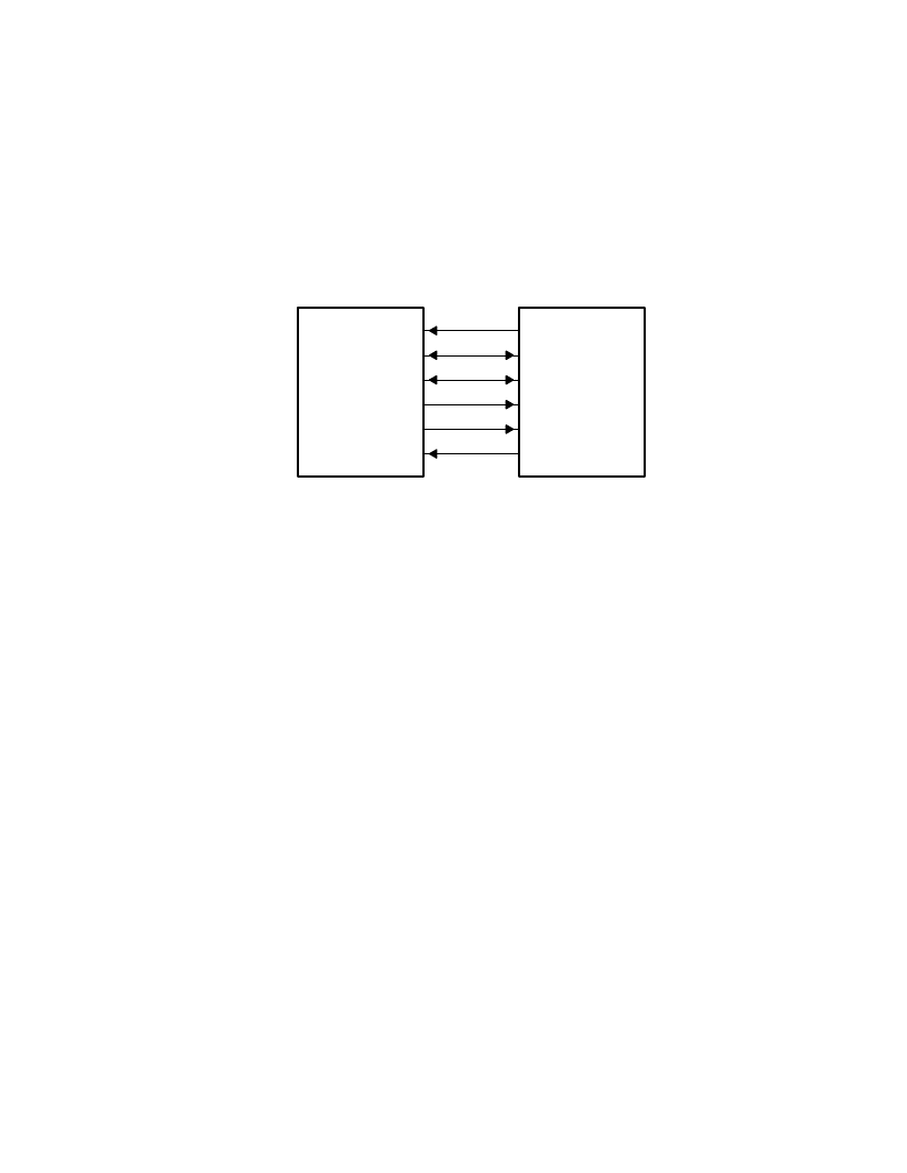
The interface to the LLC consists of the SCLK, CTL0
–
CTL1, D0
–
D1, LREQ, LPS, and LINKON terminals on the
TSB14AA1A, as shown in Figure 6
–
1.
Link Layer
Controller
SCLK
CTL0
–
CTL1
D0
–
D1
LREQ
LPS
LINKON
TSB14AA1A
Figure 6
–
1. Block Diagram of the TSB14AA1A/LLC Interface
The SCLK terminal provides either a 49.152-MHz interface clock for S100 data transfers or 24.576-MHz interface
clock for S50 data transfers. All control and data signals are synchronized to, and sampled on, the rising edge of
SCLK.
The CTL0 and CTL1 terminals form a bidirectional control bus, which controls the flow of information and data
between the TSB14AA1A and the LLC.
The D0 and D1 terminals form a bidirectional data bus, which is used to transfer status information, control
information, or packet data between the devices. The TSB14AA1A supports S50 and S100 data transfers over the
D0 and D1 data bus.
The LREQ terminal is controlled by the LLC to send serial service requests to the PHY in order to request access
to read or write internal PHY registers, or to ask the PHY to initiate a transmit action. The PHY initiates a receive action
whenever a packet is received from the serial bus.
The LPS and LINKON terminals are used for power management of the PHY and LLC. The LPS terminal indicates
the power status of the LLC, and may be used to reset the PHY-LLC interface or to disable SCLK. The LINKON
terminal is used to send a wake-up notification to the LLC and to indicate an interrupt to the LLC when LPS is inactive.
Note that not all LLCs contain a LINKON terminal, though an external circuit to operate the wake-up mode may always
be implemented at the discretion of the designer.
The TSB14AA1A normally controls the CTL0
–
CTL1 and D0
–
D1 bidirectional busses. The LLC is allowed to drive
these buses only after the LCC has been granted permission to do so by the PHY.
There are four operations that may occur on the PHY-LLC interface: link service request, status transfer, data
transmit, and data receive. The LLC issues a link service request to read or write a PHY register, or to request the
PHY to gain control of the serial-bus in order to transmit a packet.
The PHY may initiate a status transfer either autonomously or in response to a register request from the LLC.
The PHY initiates a data transmit operation after winning control of the serial-bus following a bus-request by the LLC.
The data transmit operation is initiated when the PHY grants control of the interface to the LLC.
The PHY initiates a data receive operation whenever a packet is received from the serial-bus.
The encoding of the CTL0
–
CTL1 bus is shown in Table 6
–
1 and Table 6
–
2.
相關(guān)PDF資料 |
PDF描述 |
|---|---|
| TSB21LV03MHV | IC APEX 20KE FPGA 200K 484-FBGA |
| TSB21LV03CHV | IEEE 1394-1995 TRIPLE-CABLE TRANSCEIVER/ARBITER |
| TSB2203X6MMX30M | IC APEX 20KE FPGA 200K 240-PQFP |
| TSB2204.5X12MMX20M | IC APEX 20KE FPGA 200K 240-PQFP |
| TSB2204.5X19MMX20M | IC APEX 20KE FPGA 200K 240-PQFP |
相關(guān)代理商/技術(shù)參數(shù) |
參數(shù)描述 |
|---|---|
| TSB14C01MHV | 制造商:未知廠家 制造商全稱:未知廠家 功能描述:Transceiver |
| TSB14C01PM | 制造商:Rochester Electronics LLC 功能描述:- Bulk |
| TSB15 | 制造商:未知廠家 制造商全稱:未知廠家 功能描述:EURO TERMINAL BLOCKS |
| TSB150002DS | 制造商:TE Connectivity 功能描述: |
| TSB150004DS | 制造商:TE Connectivity 功能描述:Conn Europa Terminal Blocks 8 POS 13.5mm Screw ST Cable Mount 40A/Contact |
發(fā)布緊急采購(gòu),3分鐘左右您將得到回復(fù)。