- 您現(xiàn)在的位置:買賣IC網(wǎng) > PDF目錄98307 > TWL2214CAPFB (TEXAS INSTRUMENTS INC) 1-CHANNEL POWER SUPPLY SUPPORT CKT, PQFP48 PDF資料下載
參數(shù)資料
| 型號: | TWL2214CAPFB |
| 廠商: | TEXAS INSTRUMENTS INC |
| 元件分類: | 電源管理 |
| 英文描述: | 1-CHANNEL POWER SUPPLY SUPPORT CKT, PQFP48 |
| 封裝: | PLASTIC, TQFP-48 |
| 文件頁數(shù): | 18/39頁 |
| 文件大小: | 583K |
| 代理商: | TWL2214CAPFB |
第1頁第2頁第3頁第4頁第5頁第6頁第7頁第8頁第9頁第10頁第11頁第12頁第13頁第14頁第15頁第16頁第17頁當前第18頁第19頁第20頁第21頁第22頁第23頁第24頁第25頁第26頁第27頁第28頁第29頁第30頁第31頁第32頁第33頁第34頁第35頁第36頁第37頁第38頁第39頁

TWL2214CA
POWER SUPPLY MANAGEMENT IC AND
LiIon BATTERY CHARGE CONTROL
SLVS321A – OCTOBER 2001 – REVISED JANUARY 2002
25
POST OFFICE BOX 655303
DALLAS, TEXAS 75265
APPLICATION INFORMATION
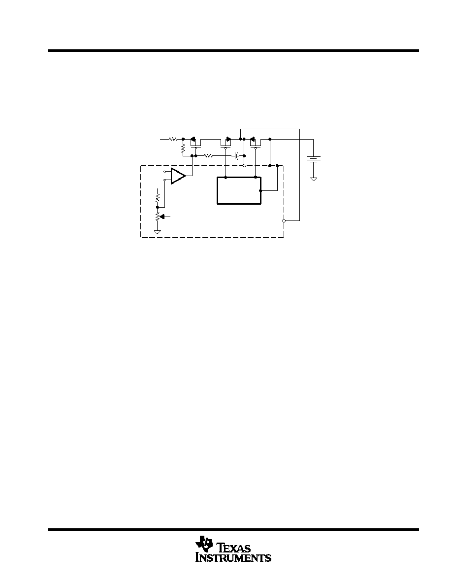
device power supply control (VDD1)
The TWL2214CA device receives device power by regulating the VCHG input to 4.1 V or 4.2 V, whenever VCHG
is available; otherwise, the device uses the VBAT input directly as device dc supply. The regulated voltage from
VCHG is programmable through the I2C interface.
BG
R1
R2
Control
Logic
Decode
VG
VG2
VG3
TWL2214CA
RS
R1: Fixed
R2: Programmable
BG: Band Gap Voltage
_
+
–
VDD1
VBAT
VDD
VCHG
Figure 15. Device Power Supply
Condition 1:
VCHG is on (VG = Active, VG2 = On, VG3 = Off)
V
DD1 +
4.1 V or 4.2 V
The TWL2214CA device sets R2 value according to the programmed voltage level (4.1 V or 4.2 V).
Condition 2:
VCHG is off and VBAT applied (VG = High, VG2 = Off, VG3 = On)
V
DD1 +
VBAT
battery charger
The TWL2214CA device provides a charger function for single cell Li-Ion battery packs. The charging activity
starts with the battery pack wake-up cycle. If the wake-up cycle completes successfully, the charger starts the
precharge function and slowly charges the battery to 3.2 V. If the battery is charged to 3.2 V within the time limit,
the charger goes into the fast charge mode. The fast charge mode has two phases: 1) constant current (CC)
mode and 2) constant voltage (CV) mode. The charger starts CC mode with the maximal charging current until
the battery voltage reaches the regulated voltage level; the charger is then switched to CV mode. During the
CV mode, the TWL2214CA device monitors the charging current; once it is below the programmed termination
current level, the charger activity is terminated. The termination current level can be programmed at 10%, 20%,
30%, 40%, or 50% of the maximum charging current at the CC mode.
相關PDF資料 |
PDF描述 |
|---|---|
| TX810IRHHT | SPECIALTY ANALOG CIRCUIT, PQCC36 |
| TX810IRHHR | SPECIALTY ANALOG CIRCUIT, PQCC36 |
| TZA1031HL | SPECIALTY CONSUMER CIRCUIT, PQFP64 |
| TZA1045TM | SPECIALTY CONSUMER CIRCUIT, PDSO16 |
| TZA1047HL/M1B | SPECIALTY CONSUMER CIRCUIT, PQFP64 |
相關代理商/技術參數(shù) |
參數(shù)描述 |
|---|---|
| TWL2214CAPFBR | 制造商:Rochester Electronics LLC 功能描述:POWER SUPPLY MANAGEMENT IC:LION - Bulk 制造商:Texas Instruments 功能描述:CHGR LI-ION/LI-POL 150MA 2.8V 48TQFP - Tape and Reel |
| TWL2217CGGMR | 制造商:Texas Instruments 功能描述: |
| TWL2217CZQER | 制造商:Texas Instruments 功能描述: |
| TWL3014CGGMR | 制造商:Fairchild Semiconductor Corporation 功能描述: |
| TWL3016B2ZQW | 制造商:Texas Instruments 功能描述: |
發(fā)布緊急采購,3分鐘左右您將得到回復。