- 您現(xiàn)在的位置:買賣IC網 > PDF目錄379475 > UC2625QTR (Texas Instruments, Inc.) Brushless DC Motor Controller PDF資料下載
參數資料
| 型號: | UC2625QTR |
| 廠商: | Texas Instruments, Inc. |
| 英文描述: | Brushless DC Motor Controller |
| 中文描述: | 無刷直流電機控制器 |
| 文件頁數: | 13/15頁 |
| 文件大小: | 313K |
| 代理商: | UC2625QTR |
13
UC1625
UC2625
UC3625
21
27
25
22
6
28
1
15
24
3
26
10k
3k
10k
2
19
20
16
11
20
μ
F
100nF
20
μ
F
100nF
+
R
OSC
33k
2200pF
C
OSC
68k
R
T
3nF
C
T
BRAKE
5nF
100nF
23
8
9
10
4
5
7
2nF
2nF
2nF
100nF
10k
5nF
240
240
17
18
14
13
12
3k
2N3906
100nF
1k
4k
TO OTHER
CHANNELS
TO OTHER
CHANNELS
10
2N3904
10
IRF9350
IRF532
3k
FROM
HALL
SENSORS
VMOTOR
+15V
+5V TO HALL
SENSORS
VREF
0.02
R
S
TO
MOTOR
0.02
R
D
REQUIRED
FOR
AVERAGE
CURRENT
SENSING
REQUIRED
FOR BRAKE
AND FAST
REVERSE
100
μ
F
+
UC3625
DIR
QUAD
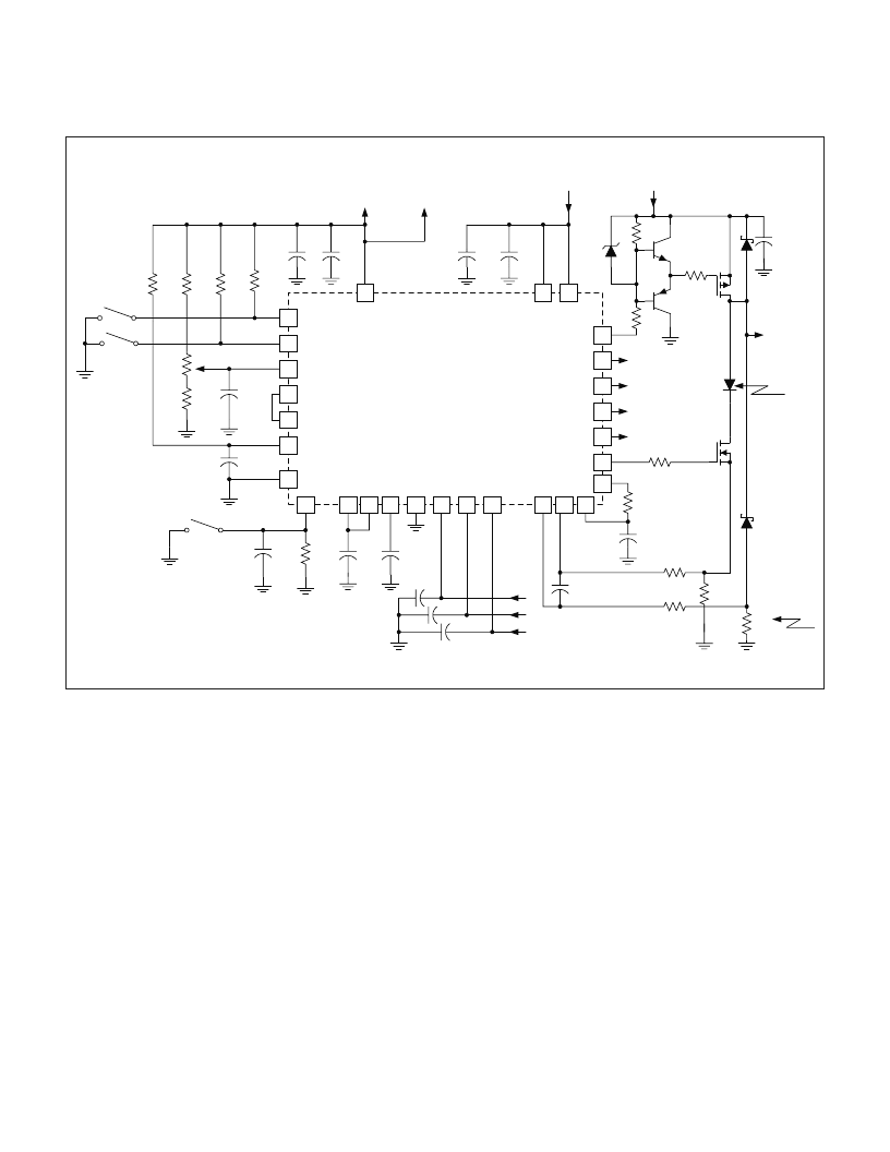
APPLICATION INFORMATION (cont.)
Figure 13. 45V/8A brushless DC motor drive circuit.
N
–
Channel power MOSFETs are used for low
–
side driv-
ers, while P
–
Channel power MOSFETs are shown for
high
–
side drivers. Resistors are used to level shift the
UC3625 open
–
collector outputs, driving emitter follow-
ers into the MOSFET gate. A 12V zener clamp insures
that the MOSFET gate
–
source voltage will never exceed
12V. Series 10
gate resistors tame gate reactance,
preventing oscillations and minimizing ringing.
The oscillator timing capacitor should be placed close to
pins 15 and 25, to keep ground current out of the capac-
itor. Ground current in the timing capacitor causes oscil-
lator distortion and slaving to the commutation signal.
The potentiometer connected to pin 1 controls PWM
duty cycle directly, implementing a crude form of speed
control. This control is often referred to as
“
voltage
mode
”
because the potentiometer position sets the aver-
age
motor
voltage.
This
controls
speed
because
steady
–
state motor speed is closely related to applied
voltage.
Pin 20 (Tach-Out) is connected to pin 7 (SPEED IN)
through an RC filter, preventing direction reversal while
the motor is spinning quickly. In two
–
quadrant opera-
tion, this reversal can cause kinetic energy from the mo-
tor to be forced into the power MOSFETs.
A diode in series with the low-side MOSFETs facilitates
PWM current control during braking by insuring that
braking current will not flow backwards through low
–
side
MOSFETs. Dual current
–
sense resistors give continu-
ous current sense, whether braking or running in
four
–
quadrant operation, an unnecessary luxury for
two
–
quadrant operation.
The 68k
and 3nF tachometer components set maxi-
mum commutation time at 140
μ
s. This permits smooth
operation up to 35,000 RPM for four
–
pole motors, yet
gives 140
μ
s of noise blanking after commutation.
UNITRODE CORPORATION
7 CONTINENTAL BLVD.
MERRIMACK, NH 03054
TEL. (603) 424-2410
FAX (603) 424-3460
UDG-99045
相關PDF資料 |
PDF描述 |
|---|---|
| UC1625N | Brushless DC Motor Controller |
| UC3711J | Dual Ultra High-Speed FET Driver |
| UC382TDTR-2 | 3A Fixed Low Dropout Linear Regulator (LDO) |
| UC2825BQTR | Double channel high side driver with analog current sense for automotive applications |
| UC2825L | Double channel high side driver for automotive applications |
相關代理商/技術參數 |
參數描述 |
|---|---|
| UC2625QTR/70040 | 制造商:Texas Instruments 功能描述: |
| UC2625QTR70040 WAF | 制造商:Texas Instruments 功能描述: |
| UC-263 | 制造商:Brainboxes 功能描述:Serial Card, 3.3/5.0V, LP uPCI, 4 x RS232, + LPT Printer Port 制造商:BRAINBOXES 功能描述:CARD SERIAL PCI 3 LP UPCI 4XRS232+LPT 制造商:Brainboxes 功能描述:LP UPCI 4XRS232 + LPT PRINTER |
| UC2633 | 制造商:TI 制造商全稱:Texas Instruments 功能描述:Phase Locked Frequency Controller |
| UC2633 WAF | 制造商:Texas Instruments 功能描述: |
發(fā)布緊急采購,3分鐘左右您將得到回復。