- 您現(xiàn)在的位置:買賣IC網(wǎng) > PDF目錄379475 > UC2625QTR (Texas Instruments, Inc.) Brushless DC Motor Controller PDF資料下載
參數(shù)資料
| 型號: | UC2625QTR |
| 廠商: | Texas Instruments, Inc. |
| 英文描述: | Brushless DC Motor Controller |
| 中文描述: | 無刷直流電機控制器 |
| 文件頁數(shù): | 9/15頁 |
| 文件大小: | 313K |
| 代理商: | UC2625QTR |
9
UC1625
UC2625
UC3625
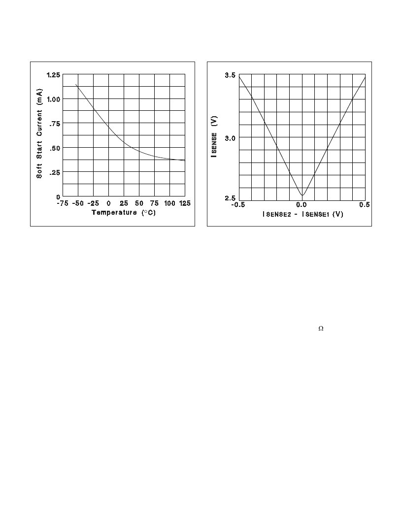
Figure 6. Soft start discharge current vs.
temperature.
TYPICAL CHARACTERISTICS (cont.)
Figure 7. Current sense amplifier transfer function.
Power Stage Design
The UC3625 is useful in a wide variety of applications,
including high-power in robotics and machinery.
power output stages used in such equipment can take a
number of forms, according to the intended perfor-
mance and purpose of the system. Below are four differ-
ent
power
stages
with
disadvantages of each shown.
The
the
advantages
and
For high-frequency chopping, fast recovery circulating
diodes are essential. Six are required to clamp the wind-
ings. These diodes should have a continuous current
rating at least equal to the operating motor current,
since diode conduction duty-cycle can be high.
low-voltage systems, Schottky diodes are preferred. In
higher voltage systems, diodes such as Microsemi
UHVP high voltage platinum rectifiers are recom-
mended.
For
In a pulse-by-pulse current control arrangement, current
sensing is done by resistor R
S
, through which the tran-
sistor's currents are passed (Fig. A, B, and C). In these
cases, R
D
is not needed. The low-side circulating di-
odes go to ground and the current sense terminals of
the UC3625 (I
SENSE1
and I
SENSE2
) are connected to R
S
through a differential RC filter. The input bias current of
the current sense amplifier will cause a common mode
offset voltage to appear at both inputs, so for best accu-
racy, keep the filter resistors below 2k
and matched.
The current that flows through R
S
is discontinuous be-
cause of chopping. It flows during the on time of the
power stage and is zero during the off time. Conse-
quently, the voltage across R
S
consists of a series of
pulses, occurring at the PWM frequency, with a peak
value indicative of the peak motor current.
To sense average motor current instead of peak cur-
rent, add another current sense resistor (R
D
in Fig. D) to
measure current in the low-side circulating diodes, and
operate in four quadrant mode (pin 22 high). The nega-
tive voltage across R
D
is corrected by the absolute
value current sense amplifier. Within the limitations im-
posed by Table 1, the circuit of Fig. B can also sense
average current.
APPLICATION INFORMATION (cont.)
相關(guān)PDF資料 |
PDF描述 |
|---|---|
| UC1625N | Brushless DC Motor Controller |
| UC3711J | Dual Ultra High-Speed FET Driver |
| UC382TDTR-2 | 3A Fixed Low Dropout Linear Regulator (LDO) |
| UC2825BQTR | Double channel high side driver with analog current sense for automotive applications |
| UC2825L | Double channel high side driver for automotive applications |
相關(guān)代理商/技術(shù)參數(shù) |
參數(shù)描述 |
|---|---|
| UC2625QTR/70040 | 制造商:Texas Instruments 功能描述: |
| UC2625QTR70040 WAF | 制造商:Texas Instruments 功能描述: |
| UC-263 | 制造商:Brainboxes 功能描述:Serial Card, 3.3/5.0V, LP uPCI, 4 x RS232, + LPT Printer Port 制造商:BRAINBOXES 功能描述:CARD SERIAL PCI 3 LP UPCI 4XRS232+LPT 制造商:Brainboxes 功能描述:LP UPCI 4XRS232 + LPT PRINTER |
| UC2633 | 制造商:TI 制造商全稱:Texas Instruments 功能描述:Phase Locked Frequency Controller |
| UC2633 WAF | 制造商:Texas Instruments 功能描述: |
發(fā)布緊急采購,3分鐘左右您將得到回復(fù)。